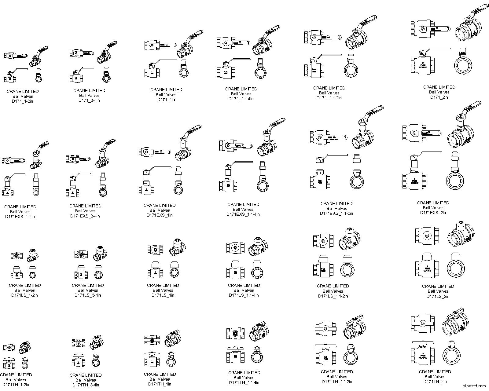
This Ball Valve CAD Block collection provides a practical drafting reference for engineers, designers, and detailers preparing piping and mechanical-system drawings. The DWG-style symbols represent Crane Limited ball valves and include side and end views for coordinated plans, risers, and schematic layouts.
Use the blocks to maintain consistent valve graphics across domestic water, utility, hydronic, mechanical-room, shop-drawing, and as-built documentation. Before placing a symbol, confirm the line size, valve orientation, connection arrangement, and project drafting convention against the applicable equipment or piping information.
This Ball Valve CAD Block collection features detailed DWG-style symbols of Crane Limited ball valves in multiple sizes. The set includes typical valve representations used in mechanical drawings, with clear side and end views that work well for piping plans, risers, and schematic layouts.
Ball valves are commonly used for isolation/shut-off in plumbing and HVAC systems because they provide quick quarter-turn operation and reliable sealing. This CAD library helps you place consistent valve symbols across your drawings and choose the correct size for each line.
Ideal for:
-
Domestic water and utility piping layouts
-
Chilled water / hot water hydronic systems
-
Mechanical room and pump room drawings
-
Shop drawings and as-built documentation
Tip: Keep these blocks in your “Valves” folder and use one standard layer/color convention for faster coordination and cleaner prints.
Source : https://www.cranefs.com
How to use the ball valve symbols
Ball valves are commonly shown where a line requires isolation or shut-off. Their quarter-turn operation makes them useful for indicating service points that may need to be opened or closed during maintenance, commissioning, or system operation. The CAD block communicates the valve location and representation; it does not replace the project specification, manufacturer documentation, or engineering review.
Coordinate the valve with the piping layout
- Choose the view that best matches the drawing type, such as a side view for a piping run or an end view for a schematic or layout condition.
- Check that the symbol is placed on the correct pipe segment and does not obscure fittings, equipment tags, dimensions, or access information.
- Coordinate valve locations with nearby pumps, equipment, drains, vents, supports, insulation, and maintenance clearances shown elsewhere in the project documentation.
- Confirm the selected valve size and connection details from the project schedule or manufacturer information rather than relying on the graphic alone.
Keep drafting standards consistent
Store the block with other valve CAD resources and apply the project’s established layer, color, lineweight, and annotation conventions. Consistent graphics make piping plans easier to review and help reduce discrepancies between design drawings, shop drawings, and as-built records.
Related piping reference topics
This resource can be reviewed alongside references for pipe fittings, flanges, piping symbols, valve terminology, and CAD/DWG drafting practices. These related topics help connect the valve symbol to the surrounding piping arrangement without treating a drawing block as a substitute for design verification.
Ball Valve CAD Block FAQ
What is included in this ball valve CAD block collection?
The collection includes DWG-style symbols of Crane Limited ball valves in multiple sizes, with side and end views intended for mechanical and piping drawings.
Where can these ball valve symbols be used?
They can support domestic water and utility layouts, chilled-water and hot-water hydronic drawings, mechanical-room and pump-room plans, shop drawings, and as-built documentation.
Does the CAD symbol define the valve’s engineering requirements?
No. The block is a drafting resource that represents the valve in a drawing. Confirm pressure, temperature, materials, connections, service compatibility, and other requirements using the project specification and manufacturer information.
How should the blocks be managed in a CAD project?
Keep the files in a dedicated valves folder and apply one project-approved layer and color convention. Review inserted blocks for scale, orientation, visibility, and coordination with the surrounding piping.