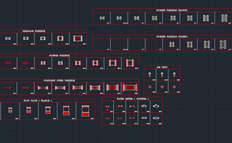
Use this flexible pipe fittings CAD block collection to speed up plumbing, HVAC, and mechanical-room drafting. The DWG brings flexible connectors and related fitting symbols into one practical reference set for plan views, risers, schematics, and coordination drawings.
Along with flexible pipe representations, the library includes air vent, flanged foot valve, and screwed water meter blocks. These details can help maintain a consistent MEP CAD library while keeping pump-room and utility-piping drawings easier to read.
This CAD block set provides a practical library of flexible pipe connectors and common plumbing/HVAC fittings used in pump rooms, mechanical spaces, and utility piping layouts. The DWG includes multiple connector types and sizes, making it easy to represent flexible joints and accessories clearly in plan and schematic drawings.
Included block categories typically cover:
-
Drainage Flexible connections
-
Rubber Flexible connectors (multiple sizes and variants)
-
Stainless Steel Flexible connectors for higher durability applications
-
Rubber Flexible (Mason / Toxen) style variations for different specs
-
Air Vent symbols for piping venting and air release
-
Foot Valve (Flange) blocks for suction lines
-
Water Meter (Screwed) blocks for domestic/utility metering
These blocks are ideal for:
-
Pump suction/discharge details (reducing vibration transfer)
-
Plumbing and HVAC piping plans, schematics, and risers
-
Mechanical room shop drawings and coordination sets
-
Standardizing your MEP CAD library with consistent symbols
How to use these flexible pipe and fitting blocks
Choose the block that matches the intended connection or accessory, then verify its orientation, insertion point, layer, and drawing scale before placing it in a project. The supplied symbols are drafting resources; they do not replace the project specification, equipment connection data, approved submittals, or engineering review.
Connector categories in the DWG
- Drainage Flexible connections for drainage-related layouts.
- Rubber Flexible connectors with multiple sizes and variants.
- Stainless Steel Flexible connectors for applications calling for that material representation.
- Rubber Flexible (Mason / Toxen) style variations where the project specification requires a particular block style.
Accessory symbols and drawing coordination
- Air Vent symbols identify piping venting and air-release points.
- Foot Valve (Flange) blocks represent a flanged foot valve on a suction-line detail.
- Water Meter (Screwed) blocks represent a screwed connection arrangement for domestic or utility metering.
For pump suction and discharge drawings, use the flexible connector symbols to show the intended arrangement clearly, then coordinate the actual installation with equipment requirements and the piping design. Related references on pipe fittings, flanges, pipe schedules, and HVAC piping layouts can help complete the drafting workflow.
CAD coordination checklist
- Confirm the block represents the required connector or fitting type.
- Check the connection orientation against the adjoining pipe and equipment.
- Match the drawing’s units, layer standards, lineweight conventions, and annotation practice.
- Review clearance, access, and maintenance space in the coordinated mechanical layout.
- Keep the block graphic separate from project-specific dimensions and specification notes unless those details have been verified.
Frequently asked questions
What is included in this flexible pipe CAD block set?
The set includes drainage flexible connections, rubber flexible connectors, stainless steel flexible connectors, rubber flexible style variations, air vent symbols, flanged foot valve blocks, and screwed water meter blocks.
Can these blocks be used for pump-room drawings?
Yes. The source set is intended for pump suction and discharge details, mechanical-room shop drawings, plumbing and HVAC plans, schematics, risers, and coordination sets. Confirm the final arrangement against the project design and equipment documentation.
Do the CAD blocks define the connector’s engineering performance?
No. A DWG symbol communicates drafting intent and geometry representation. It does not establish pressure rating, movement capability, material compliance, installation limits, or suitability for a specific design.
What should be checked before inserting a block into a drawing?
Check the connector or accessory type, orientation, connection representation, units, scale, layer, and coordination with adjacent piping and equipment. Also compare the drawing against the approved project documents.
Why use standardized flexible fitting symbols?
Consistent symbols make plans, risers, schematics, and mechanical-room coordination drawings easier to interpret. They also help maintain a reusable MEP CAD library across related drafting tasks.