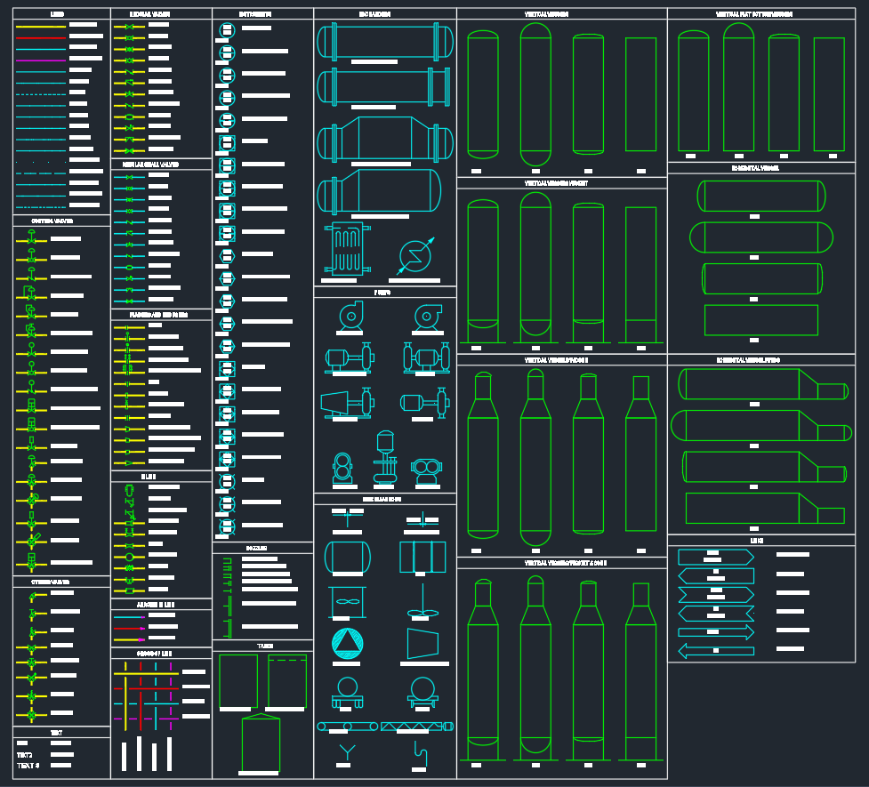
P&ID Symbols are essential graphical representations used in engineering drawings to describe process systems in industries such as oil and gas, chemical plants, power generation, and manufacturing. These symbols provide a universal method for engineers and designers to communicate how equipment, instruments, and pipelines are interconnected within a process. A well-drafted P&ID (Piping and Instrumentation Diagram) ensures efficient design, accurate construction, and effective maintenance.
Introduction
A P&ID (Piping and Instrumentation Diagram) is a detailed schematic that displays the piping layout and associated instrumentation of a process system. It shows every valve, pump, pipeline, and sensor used in a plant’s operation. P&ID symbols are standardized graphical icons that make it easier to interpret and create these diagrams accurately. Common standards include ISA S5.1 and ISO 10628, which define consistent symbol usage across different engineering disciplines.
Key Components of P&ID Symbols
P&ID symbols are grouped according to the type of component they represent. Below are some of the most frequently used categories:
1. Process Equipment Symbols
These include symbols for essential industrial equipment such as pumps, compressors, heat exchangers, tanks, and reactors. Each symbol provides details like equipment type, function, and connection points. For example, a centrifugal pump symbol shows suction and discharge nozzles, while a heat exchanger symbol indicates tube and shell flow paths.
2. Valve Symbols
Valves control the flow of fluids in a process system. Common symbols include gate valves, globe valves, ball valves, butterfly valves, and check valves. Specialized control valves are also shown with actuators and positioners to indicate automation or manual control.
3. Instrumentation Symbols
Instrumentation symbols represent measuring and control devices such as pressure gauges, flow transmitters, temperature sensors, and control loops. Each instrument has a unique tag number that helps identify its role within the control system. These symbols help engineers understand how the process is monitored and controlled.
4. Piping and Line Symbols
Piping symbols define how different lines connect between components. They include representations for pipes, fittings, elbows, reducers, tees, and line numbers. Line types also vary based on service, such as process lines, instrument air, or utility connections.
5. Control and Signal Lines
Control lines in P&IDs indicate how signals flow between instruments and controllers. Different line styles (solid, dashed, dotted) represent various types of signals such as pneumatic, hydraulic, electrical, or digital communication.
How to Use P&ID Symbols in CAD Drawings
When creating a P&ID drawing in AutoCAD or any CAD software, using standardized P&ID symbols ensures clear communication among engineering teams. Most designers use preloaded symbol libraries in DWG format to speed up the process. Symbols can be inserted directly into a drawing to build a system layout efficiently.
Here’s how to use P&ID symbols effectively:
- Start with a template: Use a base drawing with predefined layers for lines, equipment, and annotations.
- Insert symbols: Drag and drop standardized P&ID symbols into your drawing using CAD blocks or tool palettes.
- Tag components: Assign identification tags to each element for easy reference during construction or maintenance.
- Maintain consistency: Follow project-specific or international standards (ISA, ISO, or DIN) to keep symbols uniform.
- Cross-check connections: Ensure that every instrument and line has a logical connection path to avoid design errors.
Download Section
For professionals creating process schematics, having a reliable library of P&ID symbols in AutoCAD DWG format saves time and ensures accuracy. This collection includes symbols for pumps, valves, fittings, instruments, tanks, and other essential components used in industrial design.
Conclusion
P&ID symbols are a vital part of process design and documentation in mechanical, electrical, and instrumentation engineering. By using standardized and well-organized symbols in DWG drawings, engineers can communicate design intent clearly across teams and disciplines. Whether you are designing a new plant or updating an existing one, accurate P&ID symbols ensure reliability, clarity, and compliance with engineering standards. Download a complete DWG set to enhance your workflow and produce professional, ready-for-review P&ID drawings with confidence.