Category: P&ID
A piping and instrumentation diagram (P&ID) is a detailed diagram in the process industry which shows the piping and process equipment together with the instrumentation and control devices.
Superordinate to the P&ID is the process flow diagram (PFD) which indicates the more general flow of plant processes and the relationship between major equipment of a plant facility.
-
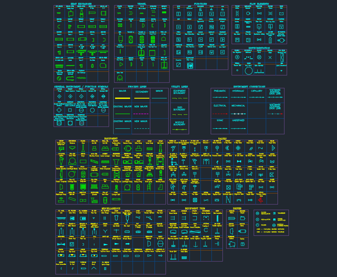
P&ID Symbols Legend CAD Block (Valves, Equipment, Instruments & Lines)
-

Piping and Instrumentation Diagram (P&ID) Of Fuel Gas System
-

P&ID Symbols | Piping and Instrumentation Diagram
-

Piping and Instrumentation Diagram (P&ID) of Fuel Gas Compressor
-

P&ID of Nitrogen Generation Plant (PSA N₂ Plant)
-
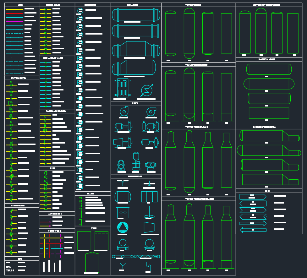
P&ID Symbols | DWG Library for Process & Instrumentation Diagrams
-

Pump Symbols Legend CAD (P&ID / MEP Pumps, Fans & Compressors)
-

Valve Symbols Legend CAD (P&ID / MEP Valves & Instruments)
-

Peripheral Symbols Legend CAD (P&ID Conveyors, Separators & Equipment)