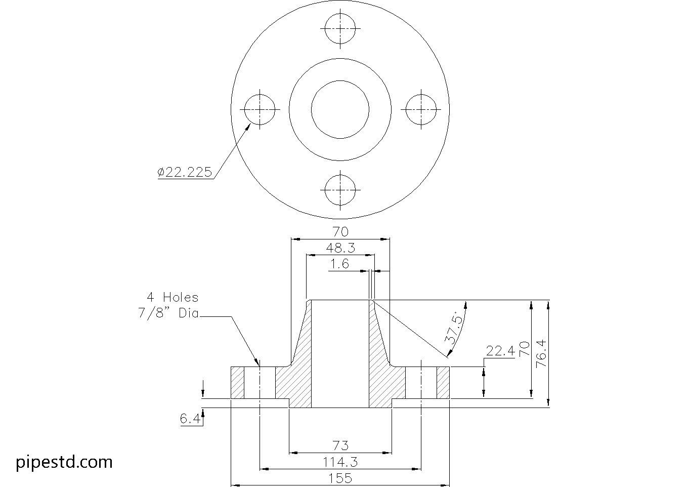
This reference provides the dimensional and connection details for a Weld Neck Flange 1 1/2 Inch Class 400. Use the listed values for drafting, piping layout review, flange identification, and preliminary fabrication coordination.
The page also explains how the weld neck hub, bore, bolt pattern, and raised face relate to the assembled piping connection. For related design work, compare this reference with the applicable pipe schedule, flange dimensions, gasket selection, and CAD/DWG piping resources.
Weld Neck Flange 1 1/2″ Class 400
Weld Neck Flange 1 1/2″ Class 400 is widely used in piping systems that require strong, leak-resistant flange connections. It features a long tapered hub that provides excellent stress distribution and is commonly applied in process piping, utility lines, and industrial systems where welding strength and reliability are important.
This dimension data is based on ANSI / ASME B16.5-2020.
Weld Neck Flange 1 1/2″ Class 400 Dimensions
- Reference Standard: ANSI / ASME B16.5
- Nominal Pipe Size (NPS):1 1/2″
- DN Size: DN40
- Outside Diameter:155mm
- Flange Thickness:22.4mm
- Hub Diameter:70mm
- Bore Diameter: varies depending on pipe schedule and pipe wall thickness
- Raised Face Diameter:73mm
- Weight: 3.7kg
- Number of Bolts:4
- Stud Bolt Size: 3/4″ UNC (or M20) x 110 Long
- Hole Diameter: 7/8″ (22.225mm)
What Is a Weld Neck Flange?
A weld neck flange is a type of pipe flange designed with a long tapered hub that is welded directly to the pipe. This design helps reduce stress concentration at the flange base and provides better strength under pressure, temperature fluctuation, and cyclic loading.
Common Applications
Weld Neck Flange 1 1/2″ Class 400 is commonly used for:
- Process piping systems
- Oil and gas lines
- Water and utility piping
- Higher pressure service
- Pressure piping connections
- Industrial fabrication and maintenance work
CAD Drawing Download
This page includes the CAD drawing file for Weld Neck Flange 1 1/2″ Class 400, which can be used for drafting, detailing, piping layout coordination, and fabrication reference.
Available Weld Neck Flange Class 400 Sizes
This size is part of the Weld Neck Flange Class 400 series. Check other sizes in the same category to find matching dimension data and CAD files for your project.
Notes
Before fabrication or installation, always confirm the latest project requirements, flange material specification, pipe schedule, bore size, gasket type, bolt length, and applicable pressure-temperature rating.
How to Read This Weld Neck Flange Reference
The dimensional list identifies the flange envelope, hub geometry, facing detail, bolt arrangement, and connection hardware. These details are useful when checking clearances, coordinating a pipe spool, preparing a fabrication drawing, or confirming that mating flanges share the same drilling pattern.
Bore and Pipe Schedule
The bore is not treated as a single universal value in this reference because it depends on the pipe schedule and wall thickness. Confirm the connected pipe specification before selecting or modeling the bore. A flange that matches the nominal pipe size can still require a different bore treatment for a particular wall thickness.
Hub, Welding, and Stress Distribution
The tapered hub provides a gradual transition between the flange and pipe. During engineering review, the weld detail, pipe wall, material specification, and fabrication procedure should be considered together. The dimensional data supports coordination, but it does not replace project-specific pressure, temperature, stress, or welding verification.
Bolting and Mating Components
Use the listed stud bolt designation, length, hole diameter, and bolt count when checking the flange connection. Confirm the project bolting convention before procurement, especially where inch and metric designations appear together. Bolt length should also be checked against flange thickness, gasket arrangement, washers, nuts, and the required thread engagement.
CAD and Drafting Use
The downloadable DWG can support layout development, detailing, and visual coordination. Before issuing a fabrication drawing, verify the model against the project specification and the applicable flange standard. Also check mating flange orientation, gasket seating, pipe centerline alignment, and access for tightening.
Selection Checklist
- Confirm nominal pipe size and connected pipe schedule.
- Verify bore compatibility with the actual pipe wall thickness.
- Match the flange class and facing arrangement with the mating component.
- Check material, gasket, stud, nut, washer, and welding requirements.
- Review the project pressure-temperature basis and applicable standard requirements.
- Use the CAD file as a drafting aid, then complete an engineering verification before fabrication.
Frequently Asked Questions
What is a weld neck flange?
A weld neck flange has a tapered hub and is welded directly to the pipe. Its geometry provides a gradual transition that can help reduce local stress concentration compared with less-integrated flange configurations.
Does the listed bore apply to every pipe schedule?
No. The bore must be checked against the connected pipe schedule and wall thickness. Confirm this interface before ordering, modeling, or welding the flange.
What should be checked before using the listed bolt size?
Confirm the bolt designation, length, hole clearance, gasket thickness, washers, nuts, flange arrangement, and project bolting requirements. The mating flange must have a compatible drilling pattern.
Can the DWG be used directly for fabrication?
The DWG is useful for drafting and coordination, but it should be reviewed against the project specification, applicable standard, material requirements, and approved fabrication details before release.
Does Class 400 alone establish the allowable working pressure?
No. The applicable pressure-temperature rating depends on the relevant standard, flange material, service temperature, and project requirements. Confirm the complete rating basis during engineering review.