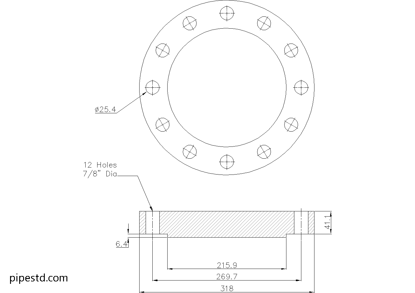
This reference page summarizes the published dimensions and installation-related details for a Blind Flange 6 Inch Class 400. Use it as a quick drafting, procurement, and piping-layout reference, while treating the source values on this page as the controlling local data.
The page also explains what a blind flange does, how to interpret the listed dimensional fields, and what to verify before fabrication or installation. For related work, connect this reference with PipeSTD resources covering flange dimensions, pipe schedules, piping terminology, and CAD/DWG files.
Blind Flange 6″ Class 400
Blind Flange 6″ Class 400 is used to seal the end of a piping system or close off a flange connection in Class 400 service. It is a solid flange without a center bore and is commonly used in industrial piping systems, maintenance isolation points, and future pipeline expansion connections where a higher pressure rating is required.
This dimension data is based on ANSI / ASME B16.5-2020.
Blind Flange 6″ Class 400 Dimensions
- Reference Standard: ANSI / ASME B16.5
- Nominal Pipe Size (NPS): 6″
- DN Size: DN150
- Flange Thickness: 41.1mm
- Weight: 28kg
- Stud Bolt Size: 7/8″ UNC (or M24) x 150 Long
- Number of Bolts: 12
- Hole Diameter: 1″ (25.4mm)
What Is a Blind Flange?
A blind flange is a blank flange used to close the end of a pipeline, vessel nozzle, or equipment connection. It provides a secure shutoff point and is often selected when future maintenance, inspection, or line extension may be required.
Common Applications
Blind Flange 6″ Class 400 is commonly used for:
- Pipe end closure
- Equipment isolation
- Valve and nozzle blanking
- Maintenance shutdown work
- Process and utility piping systems
- Higher pressure piping applications
CAD Drawing Download
This page includes the CAD drawing file for Blind Flange 6″ Class 400, which can be used for drafting, detailing, and piping layout coordination.
Available Blind Flange Class 400 Sizes
This size is part of the Blind Flange Class 400 series. Check other sizes in the same category to find matching dimension data and CAD files for your project.
Notes
Before fabrication or installation, always confirm the latest project requirements, flange material specification, gasket type, bolt length, and applicable pressure-temperature rating.
How to Read the Blind Flange Reference
A blind flange has no center bore. Unlike a flange intended to connect directly to an open pipe bore, it forms a solid closure at a flanged connection. The listed nominal size identifies the piping size association, while the flange class identifies the pressure-class designation used for selecting compatible components and checking project requirements.
What the Listed Dimensions Mean
- Flange thickness: The axial thickness of the flange body, used for general arrangement, clearance, and connection detailing.
- Weight: The published reference weight for handling, support, shipping, and material planning. Actual delivered weight can vary with material, facing details, coating, and manufacturing tolerances.
- Stud bolt size and length: The stated fastener designation for the connection. Confirm thread form, material, usable thread engagement, gasket thickness, flange facing, and assembly requirements before ordering.
- Number of bolts: The required bolt count shown by the source data. It should be coordinated with the mating flange and the applicable project specification.
- Hole diameter: The listed clearance-hole diameter in the flange. This is not the same as the stud nominal diameter and should be checked against the selected fasteners and fabrication details.
Coordination With Mating Components
A blind flange is only one part of a bolted flange joint. Before release for fabrication, compare the flange class, nominal size, bolt pattern, hole clearance, facing arrangement, gasket selection, and material specification with the mating flange and piping design. Do not use a dimensional reference alone to establish an allowable operating pressure or temperature.
CAD and Drafting Use
The downloadable DWG can support preliminary layout, detailing, and coordination. Verify the drawing against the published reference data and project requirements before using it for fabrication, because CAD geometry may not represent every material, facing, gasket, or installation condition.
Related Reference Opportunities
Readers comparing this item with other flange types may also need references for raised-face and flat-face flanges, flange bolt patterns, pipe dimensions, and pressure-class terminology. These are natural internal-link destinations for improving selection and design workflow without duplicating the local dimension list.
Blind Flange 6 Inch Class 400 FAQ
What is the main purpose of a blind flange?
It closes the end of a piping run, equipment nozzle, valve connection, or other flanged opening. It can also provide a removable closure for isolation, maintenance, inspection, or future line changes.
Does a blind flange have a center bore?
No. A blind flange is a solid flange. Its face closes the opening rather than allowing fluid to pass through a pipe bore.
Can this blind flange be used with any mating flange?
No. Compatibility must be checked using the nominal size, pressure class, bolt pattern, hole clearance, facing, gasket arrangement, material specification, and project requirements. The mating component should be verified before installation.
Does the listed bolt size establish the complete bolting requirement?
It provides the source reference for the stud-bolt designation and length, but the final bolting requirement should also account for material, thread condition, gasket thickness, flange configuration, tightening procedure, and applicable project specifications.
Is the listed weight suitable for lifting planning?
It is a useful reference for preliminary handling and logistics. Confirm the actual manufactured item, accessories, packaging, and lifting method before planning a lift.
What should be checked before using the DWG?
Check the drawing against the published dimensions, mating flange, gasket and bolting arrangement, material requirements, and the latest approved project documents. Use engineering review for any fabrication or pressure-boundary decision.