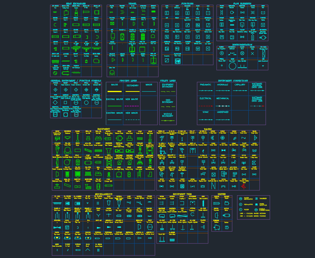
A clear P&ID depends on more than placing equipment and piping on a sheet. Symbols, line types, instrument connections, and valve representations must communicate the intended process information consistently. This P&ID Symbols Legend CAD Block provides a convenient reference for drafting, reviewing, and developing process and utility documentation.
Use the legend alongside your project’s approved drafting practices, drawing notes, and design documentation. It can also support related work involving P&ID terminology, piping layouts, equipment identification, and CAD standards.
If you’re building P&ID drawings or process schematics, this P&ID Symbols Legend CAD block gives you a solid reference sheet to keep your drawings clear and consistent. It combines the most common symbol groups used in industrial, utility, and plant documentation, so you can standardize your diagram style across all sheets.
What’s included in this P&ID legend
This symbol sheet covers a wide range of categories typically needed in process drawings, including:
-
Heat exchanger symbols
-
Vessel symbols
-
Pump and equipment symbols
-
Flow elements
-
Instrumentation symbols
-
General instrument / function symbols
-
Process lines and utility lines
-
Instrument connections
-
Valve symbols
-
Driver symbols
-
Equipment trim / miscellaneous items
Why this legend is useful
Instead of collecting symbols from different files, you can use one organized reference sheet to keep your P&ID notation uniform. That helps when you’re reviewing drawings, coordinating with other disciplines, or preparing project standards for future work.
Best use cases
-
Process plant and utility P&ID drawings
-
Mechanical and piping documentation sets
-
Training junior drafters on symbol standards
-
Office CAD standards and template libraries
How to use this P&ID symbol reference
A P&ID legend is a visual key: it helps readers interpret the graphical language used on a process drawing. Before placing a symbol in a drawing, confirm that its meaning, tag format, connection style, and line convention match the project or company standard. The legend is a drafting reference, not a substitute for process design information, equipment specifications, or engineering review.
What to check during drafting and review
- Symbol meaning: Verify that the selected valve, equipment, instrument, or flow-element symbol represents the intended function.
- Connections: Check how process lines, utility lines, and instrument connections enter or leave each item.
- Identification: Keep tags, notes, and equipment references consistent with the project’s document-control practice.
- Line clarity: Make sure crossing lines, signal paths, and utility connections remain readable at the drawing scale used by the project.
- CAD organization: Place reusable blocks on appropriate layers and confirm that linework, attributes, and insertion behavior work correctly in the target CAD environment.
Related PipeSTD references
For a broader drafting workflow, pair this resource with references on piping terminology, pipe dimensions and schedules, flange dimensions, and CAD/DWG resources. These subjects address the relationship between a P&ID’s process representation and the piping documentation developed during later design stages.
Important drafting limitation
Symbol appearance and usage can vary between project standards, disciplines, and software libraries. Treat this legend as an organized reference sheet, then compare it with the governing project standard before issuing drawings for coordination, construction, operation, or maintenance.
Frequently asked questions
What is a P&ID symbols legend?
A P&ID symbols legend is a reference that explains the graphical symbols and line conventions used on a piping and instrumentation diagram. It helps engineers, designers, drafters, operators, and reviewers interpret the same drawing language.
What does this CAD block include?
The source legend groups symbols for heat exchangers, vessels, pumps and other equipment, flow elements, instrumentation, process and utility lines, instrument connections, valves, drivers, and miscellaneous equipment items.
Is a P&ID the same as a piping layout?
No. A P&ID communicates process relationships, equipment, valves, instruments, and control connections. A piping layout focuses more directly on physical arrangement, routing, access, supports, and installation coordination.
Can I use the symbols without checking a project standard?
Use the file as a starting reference, but check the applicable project, company, client, or software convention before issuing a drawing. Similar functions may be represented differently across drafting systems.
Does the legend replace equipment or piping design data?
No. Symbols show function and documentation intent; they do not establish equipment performance, piping dimensions, material requirements, operating conditions, or design suitability.
Who can benefit from this reference?
Process designers, piping designers, instrumentation specialists, CAD drafters, reviewers, and junior engineers can use the legend when preparing or checking process documentation.