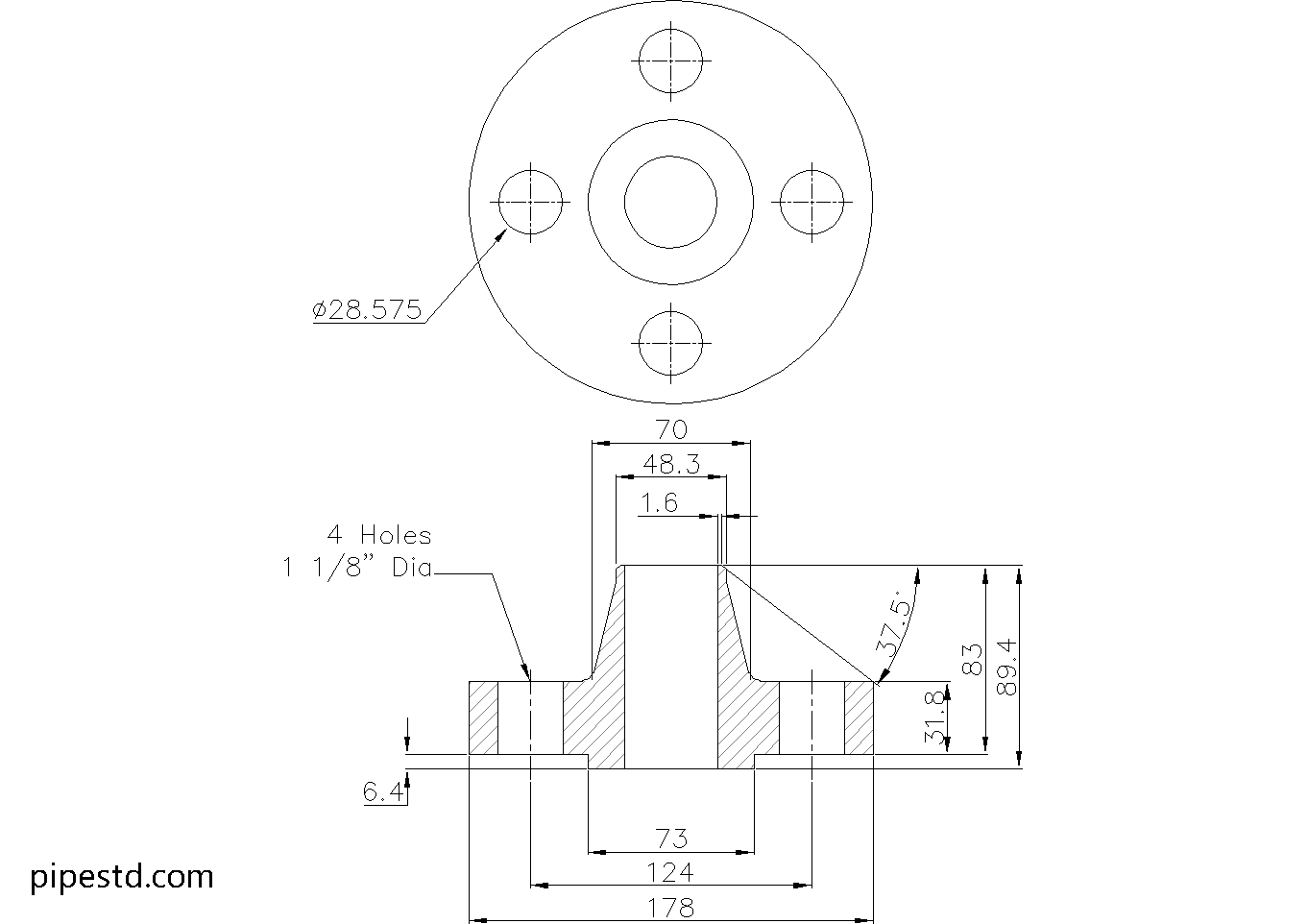
This reference page provides the dimensional details and CAD resource for a Weld Neck Flange 1 1/2 Inch Class 900. Use the values below when checking a piping layout, preparing a fabrication drawing, or coordinating the flange with pipe, gasket, and bolting requirements.
The listed flange dimensions should be read together with the applicable pipe schedule and project specification. In particular, the bore is not a single universal value because it must correspond to the pipe’s wall thickness and schedule. For related design work, also review the site’s references for pipe schedules, flange types, gasket selection, and stud bolt terminology.
Weld Neck Flange 1 1/2″ Class 900
Weld Neck Flange 1 1/2″ Class 900 is widely used in piping systems that require strong, leak-resistant flange connections under high-pressure service. It features a long tapered hub that provides excellent stress distribution and is commonly applied in process piping, utility lines, refineries, power plants, and industrial systems where welding strength and reliability are essential.
This dimension data is based on ANSI / ASME B16.5-2020.
Weld Neck Flange 1 1/2″ Class 900 Dimensions
- Reference Standard: ANSI / ASME B16.5
- Nominal Pipe Size (NPS):1 1/2″
- DN Size: DN40
- Outside Diameter:178mm
- Flange Thickness:31.8mm
- Hub Diameter:70mm
- Bore Diameter: varies depending on pipe schedule and pipe wall thickness
- Raised Face Diameter:73mm
- Weight: 5.9kg
- Number of Bolts:4
- Stud Bolt Size: 1″ UNC (or M27) x 140 Long
- Hole Diameter: 1 1/8″ (28.575mm)
What Is a Weld Neck Flange?
A weld neck flange is a type of pipe flange designed with a long tapered hub that is welded directly to the pipe. This design helps reduce stress concentration at the flange base and provides better strength under pressure, temperature fluctuation, and cyclic loading.
Common Applications
Weld Neck Flange 1 1/2″ Class 900 is commonly used for:
- Process piping systems
- Oil and gas lines
- Refinery and petrochemical piping
- Very high-pressure service
- Pressure piping connections
- Industrial fabrication and maintenance work
CAD Drawing Download
This page includes the CAD drawing file for Weld Neck Flange 1 1/2″ Class 900, which can be used for drafting, detailing, piping layout coordination, and fabrication reference.
Available Weld Neck Flange Class 900 Sizes
This size is part of the Weld Neck Flange Class 900 series. Check other sizes in the same category to find matching dimension data and CAD files for your project.
Notes
Before fabrication or installation, always confirm the latest project requirements, flange material specification, pipe schedule, bore size, gasket type, bolt length, and applicable pressure-temperature rating.
How to Read This Flange Reference
A weld neck flange is identified by its nominal pipe size and pressure class, while its physical geometry includes the flange outside diameter, thickness, hub dimensions, raised face, bolt-hole pattern, and bore. These features are used together during piping design and fabrication rather than treated as independent purchase dimensions.
Bore and Pipe Schedule
The bore should be checked against the actual pipe selected for the line. A flange may have the correct nominal size and pressure class but still require a different bore arrangement for the pipe wall thickness being used. Confirm the pipe schedule, inside diameter requirements, welding preparation, and any project machining requirements before fabrication.
Bolting and Joint Assembly
The listed bolt count, stud bolt size, length, and hole diameter describe the bolting arrangement for this reference item. They should be checked against the mating flange, gasket dimensions, washer requirements, thread engagement, and available clearance. Do not assume that a bolt will fit solely because its nominal designation appears compatible; verify the complete joint assembly.
Why the Hub Matters
The tapered hub provides a gradual transition between the pipe and flange body. This is one reason weld neck flanges are commonly selected for piping connections where welding quality, alignment, pressure service, temperature changes, or cyclic loading require careful engineering review. The flange type does not remove the need to verify material, welding procedure, inspection, and pressure-temperature requirements.
Using the CAD File
The downloadable DWG can support drafting, layout coordination, and fabrication reference. Treat the drawing as a dimensional aid and compare it with the authoritative values on this page and the project’s current specifications before issuing construction documents. Check units, insertion point, layer conventions, mating components, and the selected pipe bore in the working drawing.
Related Reference Topics
- Compare this item with other Class 900 weld neck flange sizes when developing a piping arrangement.
- Review flange facing and gasket references before detailing a bolted joint.
- Use the site’s pipe dimension and schedule tables to confirm the bore and pipe connection.
- Consult related CAD flange drawings when coordinating fittings, valves, and adjacent piping.
Frequently Asked Questions
What does NPS 1 1/2 mean on this flange?
NPS 1 1/2 identifies the nominal pipe size associated with this flange. The page also lists the corresponding DN designation as DN40. Nominal size should not be treated as the flange bore; the bore must be checked against the selected pipe schedule and wall thickness.
Why is the bore described as schedule-dependent?
Pipe with the same nominal size can have different wall thicknesses. The flange bore therefore needs to match the pipe selected for the project. Confirm the schedule, actual pipe dimensions, and welding details before ordering or fabrication.
Can the listed stud bolts be used without checking the mating flange?
No. The listed bolting information is a reference for this flange. Verify that the mating flange, gasket, hole pattern, clearances, washers, thread engagement, and project requirements are compatible before assembly.
What is the DWG file intended for?
The DWG is provided as a drafting, layout, detailing, and fabrication reference. Review its units and geometry against the page data and current project requirements before using it in issued drawings.