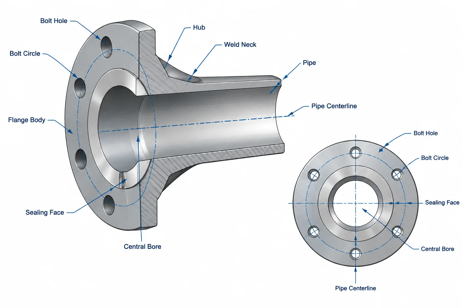
Flange dimension terminology describes several separate interfaces within one component. Bore, bolt circle, face, hub, and thickness dimensions may appear together on a drawing, but each controls a different aspect of flow, sealing, bolting, structural geometry, or pipe connection.
This reference helps drafters, designers, and technical users interpret those terms without assuming that similarly named dimensions are interchangeable. Use it to organize flange data and review CAD geometry, then confirm all project-critical information against the governing specification, approved drawing, or manufacturer documentation.
A flange drawing may appear simple, but its dimensions describe several different interfaces at once. The central opening relates to the pipe or equipment nozzle, the facing supports the gasketed joint, the bolt pattern connects the mating components, and the hub or body transfers load into the pipe.
Confusing these features can produce a CAD component that looks plausible but cannot mate with the intended flange, valve, or nozzle. This guide explains common flange dimension terminology and shows how to organize the information during modeling, drafting, and component verification. It is an interpretation guide, not a substitute for the governing standard, project piping specification, or verified manufacturer data.
The Main Dimensional Zones of a Flange
It is useful to divide a flange into functional zones rather than treating it as one solid disk:
- Flow opening: The bore through which the process fluid passes.
- Sealing interface: The flange face and any raised, recessed, grooved, or ring-joint features that interact with the gasket.
- Bolting interface: The bolt circle, bolt-hole count, hole diameter, and hole orientation.
- Structural body: The flange thickness and outside diameter.
- Pipe transition: The hub, neck, socket, thread, or lap-joint geometry connecting the flange to the adjoining component.
Each zone has a different purpose. Two flanges can have a similar outside appearance while differing in bore, facing, hub geometry, or end connection. A reliable CAD library therefore needs more than a nominal size and a pressure-class label.
Flange Outside Diameter
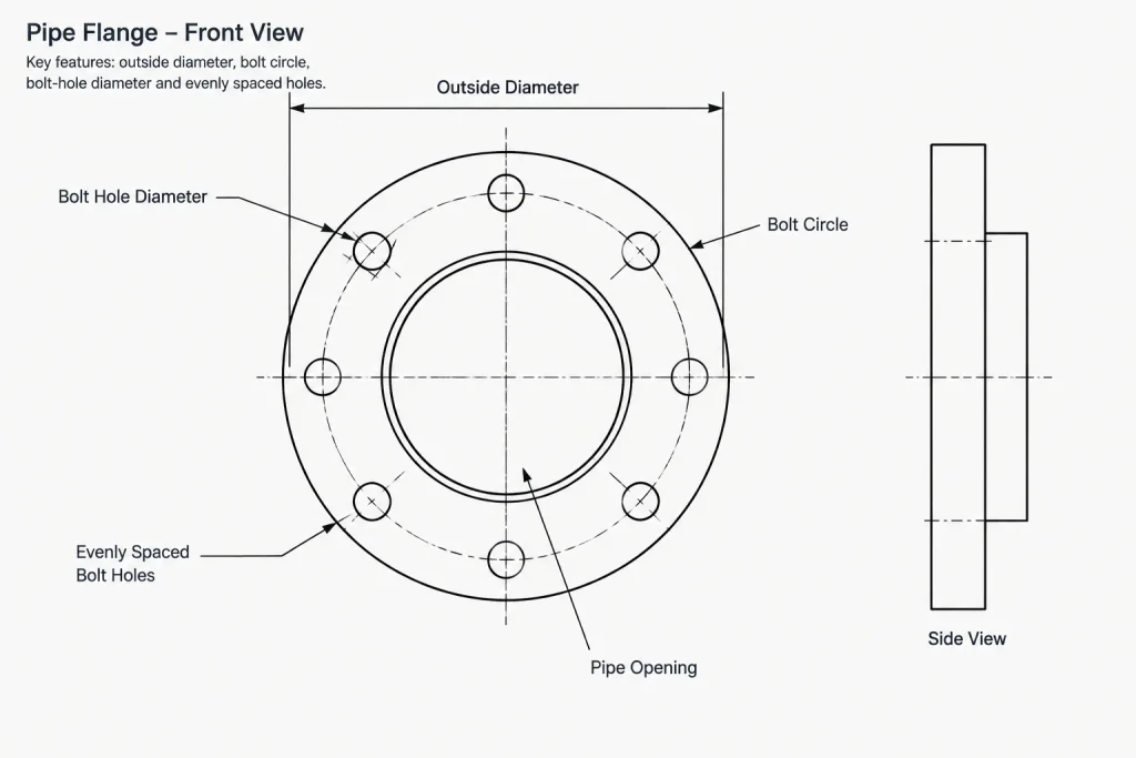
The flange outside diameter is measured across the outer edge of the flange body. It establishes the broad radial envelope but does not, by itself, define compatibility.
In layout work, the outside diameter is important for checking nearby steel, insulation, adjacent flanges, valve bodies, and tool access. It should not be confused with the bolt circle diameter or the diameter of a raised face. Those are separate concentric features.
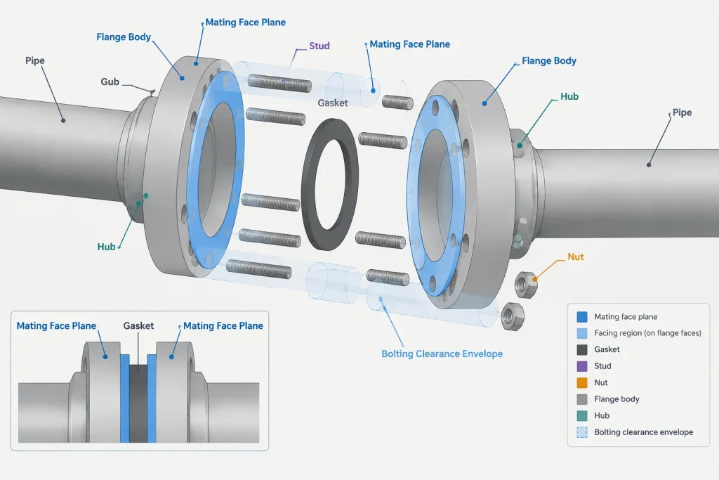
A simplified model may use the outside diameter as the visible flange envelope. However, interference reviews may also require bolt and nut envelopes because the installed joint can occupy more space than the bare flange disk.
Bore and End-Connection Opening
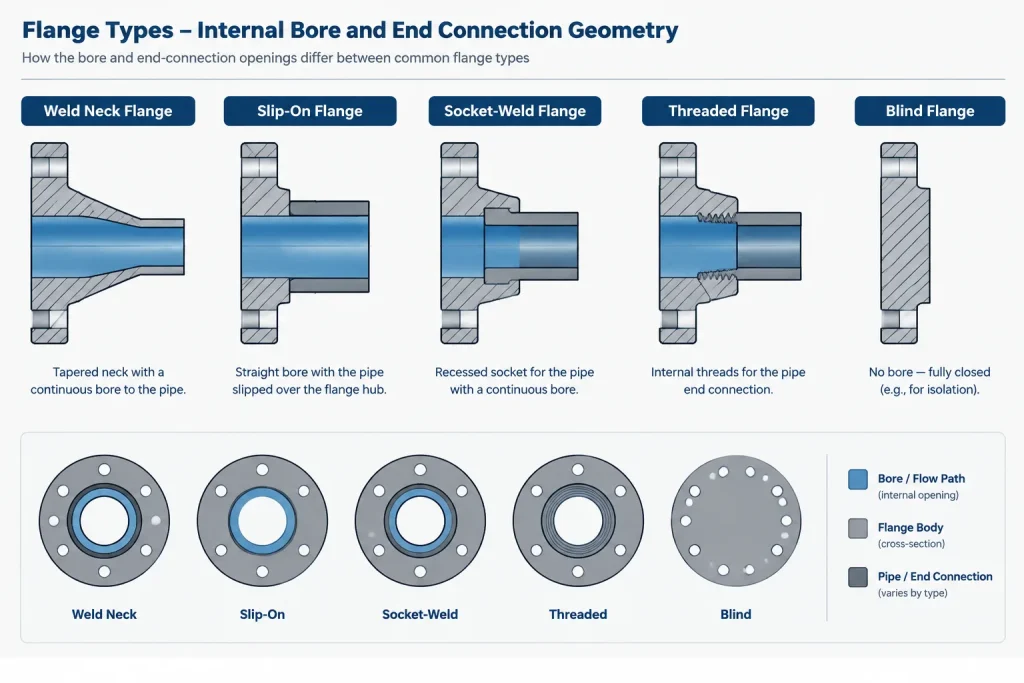
The flange bore is the central opening through the flange. Its interpretation depends on the flange type.
- On a weld neck flange, the bore continues through the neck and is commonly selected to suit the connected pipe wall or specified bore condition.
- On a slip-on flange, the opening must receive the pipe outside diameter with the required assembly relationship.
- On a socket-weld flange, the internal geometry includes a socket and a smaller passage beyond the socket shoulder.
- On a threaded flange, the central opening includes the thread form and engagement region.
- On a blind flange, there is no through-bore, although a drawing may include auxiliary tapped or drilled openings when specifically required.
The bore is not automatically equal to the nominal pipe size. Nominal size is a designation, while the actual opening is a physical dimension. Pipe schedule, flange type, machining, lining, and manufacturer-specific construction can all affect the relevant internal geometry.
Bolt Circle Diameter
The bolt circle diameter, sometimes called the pitch circle diameter, locates the centers of the bolt holes on an imaginary circle around the flange axis. It is not measured to the inside or outside edges of the holes.
A complete bolt pattern requires more than the bolt circle diameter. The drawing or component record should also identify:
- Number of bolt holes
- Bolt-hole diameter or slot geometry
- Angular spacing
- Clocking or orientation relative to a reference axis
- Any special tapped-hole or nonuniform pattern
Evenly spaced holes can usually be generated as a circular pattern in CAD. The reference angle still matters. On many piping drawings, bolt holes are arranged to straddle principal centerlines rather than placing a hole directly on a centerline. That convention must be checked against project requirements and the actual mating interface.
Bolt-Hole Diameter Is Not Bolt Diameter
The bolt hole is generally larger than the fastener passing through it. Consequently, a hole diameter should not be treated as the nominal bolt or stud diameter.
This distinction affects both modeling and material data. A flange component may need a hole diameter for geometry, a fastener diameter for the bill of materials, and a separate clearance envelope for wrenching or nut installation. Storing all three under a generic field such as “bolt size” creates avoidable ambiguity.
Flange Thickness
Flange thickness normally describes the axial thickness of the main flange body, but the measurement endpoints must be understood from the applicable drawing. A raised face, ring-joint feature, hub, or other projection may be controlled separately.
This matters when calculating a flanged-joint stack. The axial space occupied by an assembly can include two flange bodies, facing projections, a gasket or ring, and the required installed relationship between the mating faces. Simply adding two values labeled “thickness” may not represent the actual face-to-face assembly length.
For CAD placement, the most useful datum is often the mating face plane. Component length should then be built from that interface to the opposite controlled endpoint, rather than inferred from a body-thickness dimension.
Facing Diameter, Height, and Profile
The sealing face is not always the full flange diameter. A flange may include a distinct raised region, a flat full-face contact surface, a groove, or another specified facing configuration.
Relevant facing information can include:
- Facing type
- Facing outside diameter
- Projection or recess relative to the surrounding flange surface
- Groove geometry where applicable
- Surface-finish requirement
Facing dimensions should be modeled only to the level needed by the workflow. A general arrangement model may need the mating face and broad envelope, while a fabrication or manufacturer model may require the actual facing profile. Surface texture is usually documented as data or a drawing note rather than represented as literal three-dimensional serrations.
Hub, Neck, and Taper Dimensions
A hub is the thickened transition between the flange body and the pipe connection. Weld neck flanges have a prominent neck, while other flange types may have a shorter hub or no projecting hub.
Common hub-related dimensions describe:
- Diameter near the flange body
- Diameter at the pipe end
- Axial hub or neck length
- Tapered transition
- Weld-end bore and outside geometry
Hub dimensions affect clash detection, insulation envelopes, weld access, nondestructive examination access, and the total space required near equipment nozzles. A flange represented only as a flat cylinder can conceal these constraints.
Dimension Terms and Their CAD Uses
| Dimension term | What it controls | Common CAD use | Frequent mistake |
|---|---|---|---|
| Outside diameter | Outer flange body envelope | Clash and spacing checks | Using it as the bolt circle |
| Bore | Internal flow or connection opening | Section views and pipe matching | Assuming it equals nominal size |
| Bolt circle diameter | Radial location of hole centers | Circular hole pattern | Measuring to hole edges |
| Bolt-hole diameter | Physical opening for a fastener | Flange geometry | Treating it as fastener diameter |
| Flange thickness | Axial body thickness | Envelope and section geometry | Including or excluding facing without checking |
| Facing diameter | Extent of sealing-face feature | Joint and gasket representation | Equating it with flange outside diameter |
| Hub length | Axial pipe-transition geometry | Weld and clearance layout | Omitting the hub from space checks |
A Practical Flange Modeling Workflow
1. Identify the component completely
Record nominal size, flange type, pressure class or other governing designation, material requirement, facing, and end connection. Do not select geometry from nominal size alone.
2. Establish the primary datum
Use the mating face as the placement plane when the flange connects to another flanged component. Establish the pipe or nozzle centerline as the main axis. This makes replacement and alignment checks easier.
3. Separate standard-controlled and vendor-controlled data
Some flange dimensions may come from an adopted dimensional standard, while valve flanges, integral equipment flanges, specialty flanges, and modified bores may require manufacturer information. Mark uncertain fields rather than filling them by visual approximation.
4. Build concentric features independently
Model the bore, facing, bolt circle, outside diameter, and hub as distinct features driven by named parameters. Avoid deriving one diameter from another unless the verified source explicitly establishes that relationship.
5. Check the mating component
Confirm the bolt pattern, facing, bore relationship, gasket selection basis, and face-to-face placement against the actual mating flange or equipment nozzle. Matching labels do not eliminate the need to compare physical interfaces.
6. Apply the appropriate level of detail
A P&ID symbol does not need flange geometry. A layout model may need the outside envelope, face plane, hub, and approximate bolting space. Fabrication or procurement work requires verified dimensions and controlled component data. Use detail that supports the deliverable without implying unsupported accuracy.
Why Flange Dimensions Should Be Stored as Data
Parametric CAD parts are easier to audit when their dimensional fields have explicit names. Fields such as flange outside diameter, bolt circle diameter, hole count, hole diameter, face projection, bore, and hub length are clearer than anonymous parameters such as D1, D2, and L unless a controlled data dictionary defines them.
The same principle applies to drawings and spreadsheets. A dimension is useful only when its endpoints and meaning are unambiguous. Good flange records preserve the source, component identity, revision status, and whether the value is standard-based, manufacturer-specific, project-modified, or awaiting confirmation.
Final Verification Principle
Flange compatibility is a multi-feature check, not a single-size comparison. The nominal designation helps identify the component family, but the physical joint depends on the bore, face, bolt pattern, thickness, hub, and connection details working together.
For drafting and CAD, begin with controlled reference planes and clearly named dimensions. For procurement, fabrication, or installation, verify the geometry against the governing project documents and current manufacturer information. That approach prevents a visually convincing flange model from being mistaken for a confirmed project component.
How to Review an Unfamiliar Flange Drawing
Begin with the component axis and mating face rather than the outside silhouette. These references help establish where radial dimensions originate and where axial dimensions begin or end. Next, group the callouts by function: flow opening, sealing face, bolting pattern, flange body, and pipe transition.
For every callout, identify the dimension endpoints. A diameter may describe the outside body, bore, facing, hole, or circle through the hole centers. An axial dimension may describe the body alone, a facing projection, a hub, or the total distance from the mating face to another controlled point.
Do not infer a missing feature from visual proportions. Schematic views, catalog illustrations, and simplified CAD models may omit machining details or show geometry that is not intended for measurement.
Flange Data Handoff Checklist
Before releasing or reusing a flange component, confirm that its record clearly distinguishes the following information:
- Component identity: Flange type, nominal designation, class or other applicable designation, facing, material requirement, and end connection.
- Placement references: Mating face plane, component axis, and bolt-pattern orientation reference.
- Radial geometry: Outside diameter, bore, facing extent, bolt circle, and bolt-hole geometry.
- Axial geometry: Body thickness, face projection or recess, hub or neck length, and connection endpoint.
- Interface requirements: Mating bolt pattern, compatible facing arrangement, gasket basis, and bore relationship.
- Data status: Source, revision state, manufacturer dependency, project modification, and unresolved fields.
A model should not be presented as verified merely because these fields exist. Verification requires comparing the populated values and feature definitions with the documents controlling the actual component.
Choosing the Right CAD Detail
Use enough geometry to support the intended task. A layout model commonly benefits from an accurate face location, outside envelope, hub envelope, bore relationship, and bolting clearance. A detailed component used for fabrication or interface control may require additional verified features.
Keep metadata separate from physical geometry where appropriate. Facing finish, source status, and procurement notes may be essential even when they are not represented as modeled surfaces. This separation keeps the model readable while preserving information needed for review.
Frequently Asked Questions
Is flange bore the same as nominal pipe size?
No. Nominal pipe size is a designation, while bore describes a physical internal opening. The applicable bore depends on flange type, connected pipe geometry, machining, and any project or manufacturer requirements.
Where is bolt circle diameter measured?
It is measured through the centers of the bolt holes on an imaginary circle around the flange axis. It is not measured to the inner or outer edges of the holes.
Does flange thickness include the raised face?
Not necessarily. The intended endpoints must be read from the controlling drawing or dimensional source. The flange body and facing projection may be defined separately.
Can outside diameter confirm that two flanges will mate?
No. Mating compatibility also depends on the bolt pattern, facing, bore relationship, orientation, and other connection details. A similar outside envelope does not establish a compatible joint.
Why should the mating face be used as a CAD datum?
The mating face is the functional interface between connected components. Using it as a controlled placement plane makes alignment, replacement, and assembly-length checks clearer than positioning the flange from an arbitrary body surface.
Should flange-face texture be modeled as physical geometry?
Usually only when the workflow specifically requires that detail. For many layout and coordination models, the facing type and finish are better maintained as controlled data or drawing notes rather than literal surface geometry.
What should be checked before reusing a flange CAD block?
Confirm the component identity, source, revision status, face datum, bore, bolt pattern, body dimensions, hub geometry, and intended level of detail. Any unverified field should remain identified as unresolved rather than estimated from appearance.