Tag: flanges

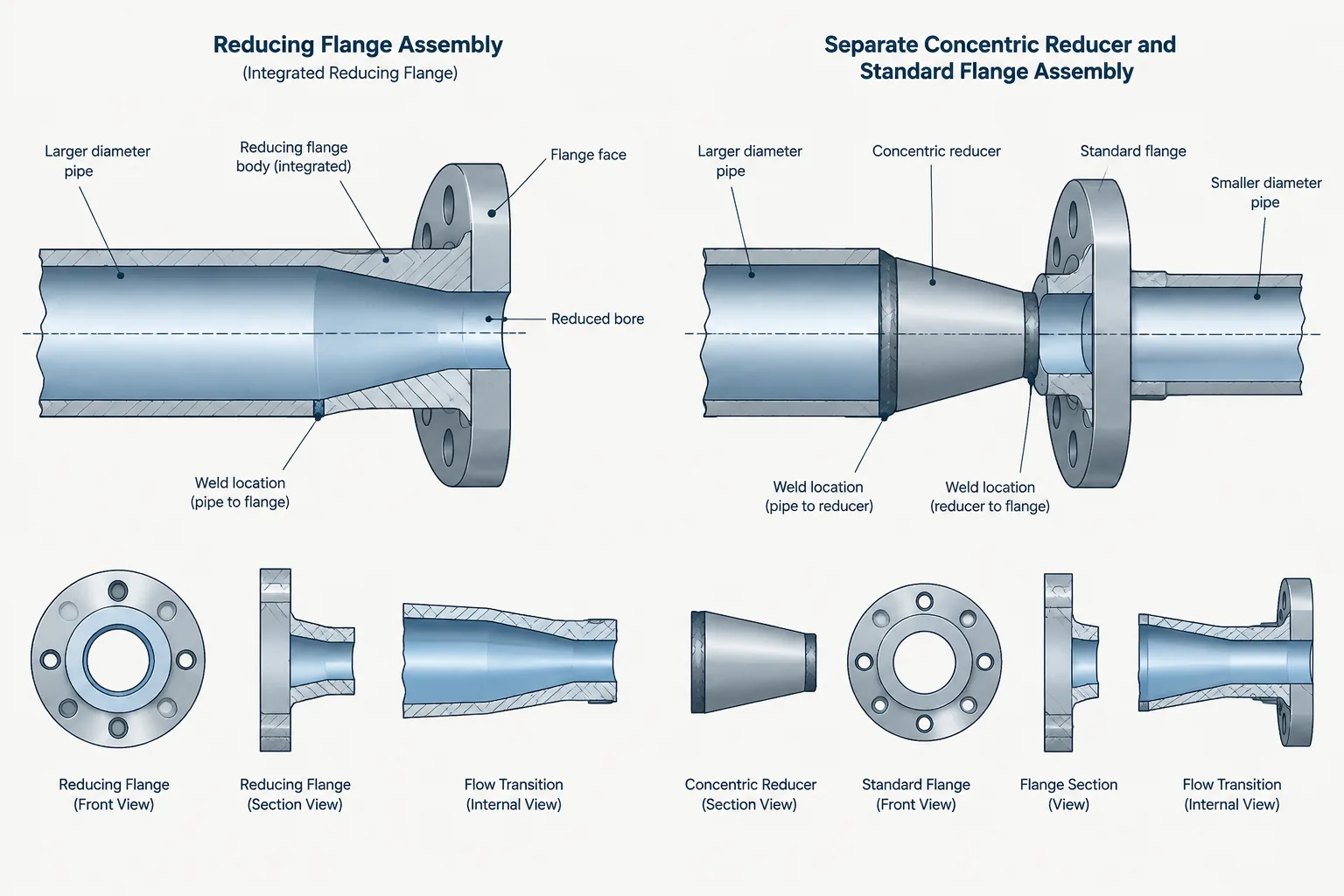
  • Reducing Flanges vs. Reducers in Piping CAD: Size Transitions, Bolt Patterns, and Layout

    Reducing Flanges vs. Reducers in Piping CAD: Size Transitions, Bolt Patterns, and Layout

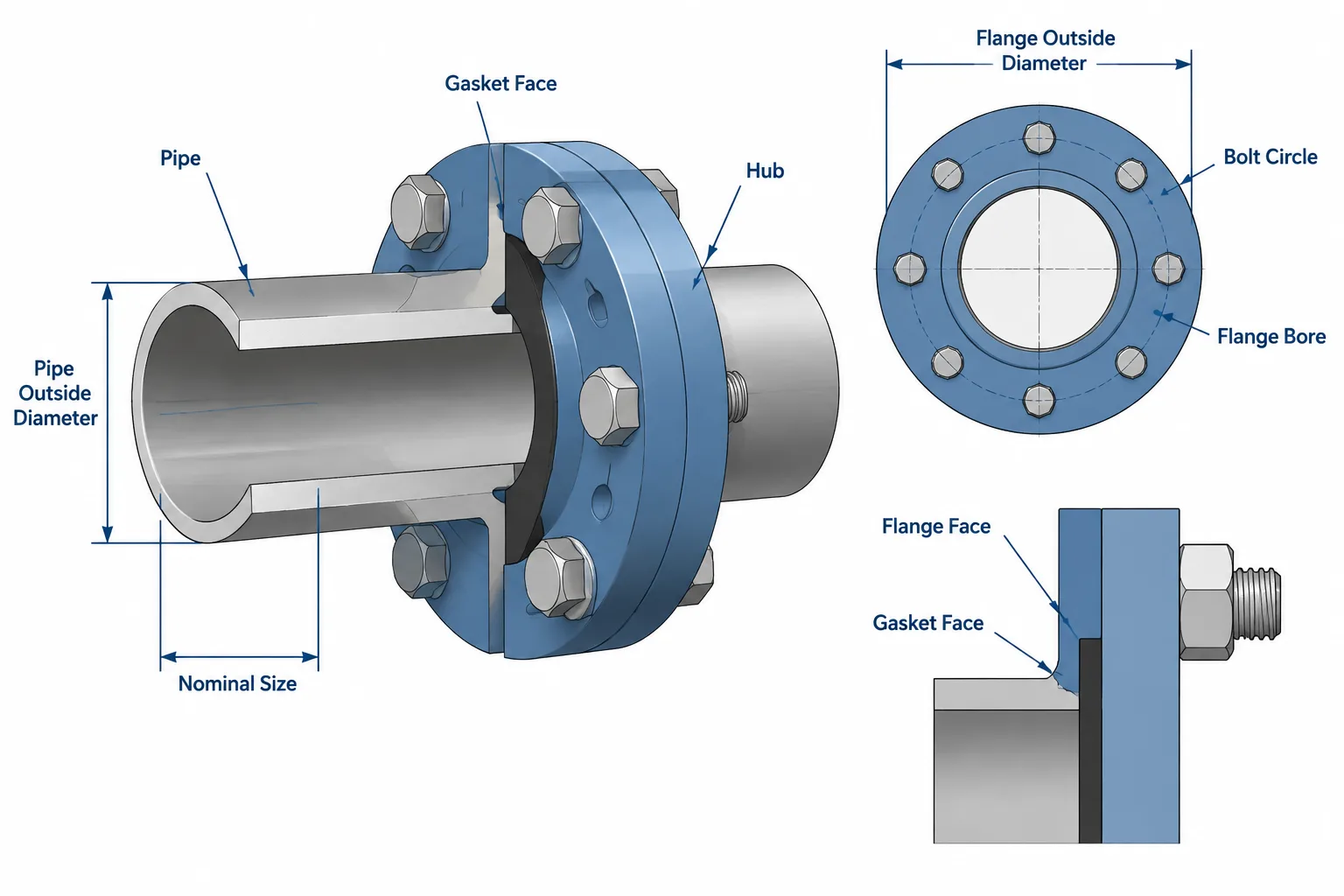
  • Flange Size vs. Pipe Size: Nominal Size, Bore, Outside Diameter, and Bolt Pattern Explained

    Flange Size vs. Pipe Size: Nominal Size, Bore, Outside Diameter, and Bolt Pattern Explained

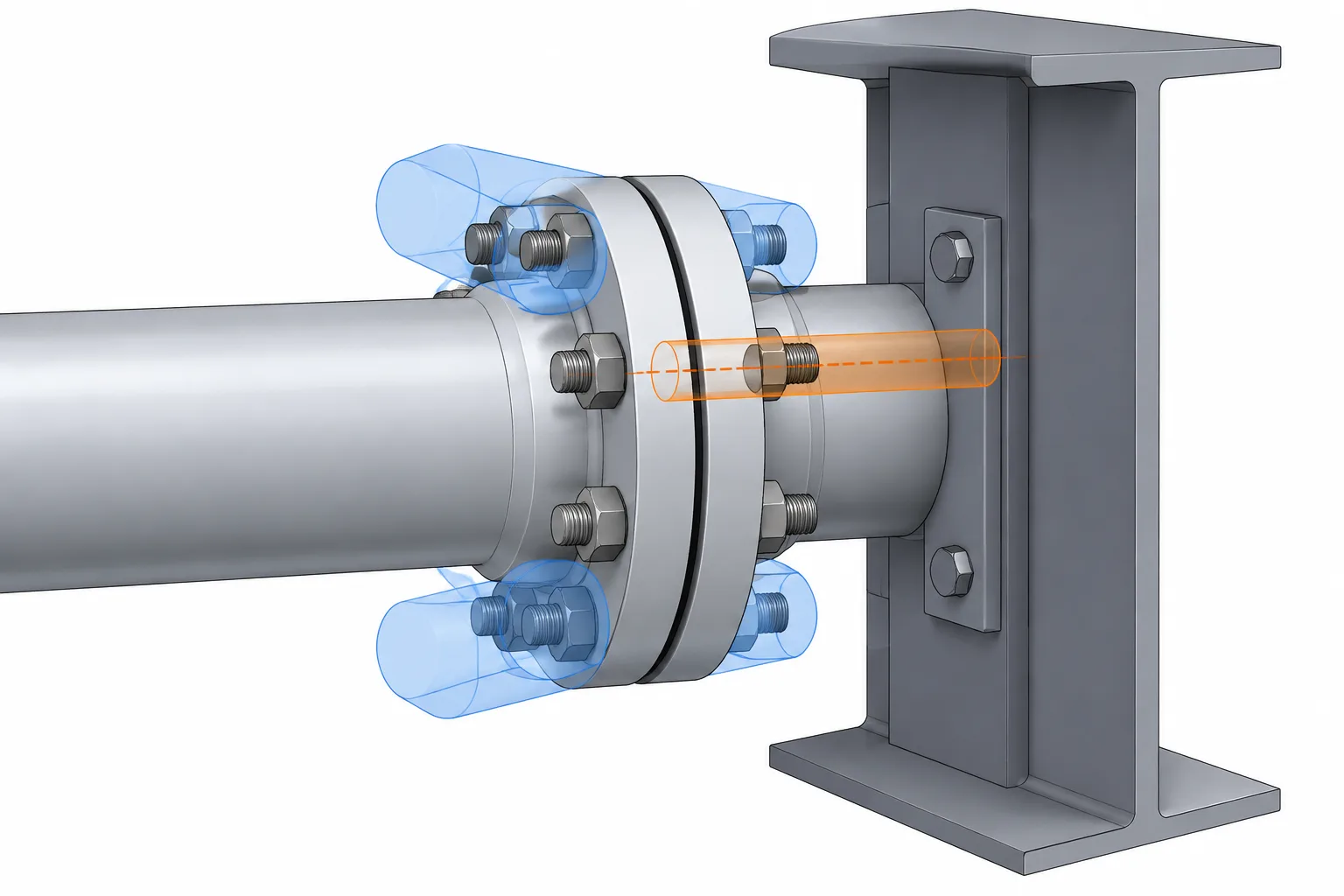
  • Flange Bolting Access in Piping CAD: Wrench Clearance, Stud Removal, and Obstruction Checks

    Flange Bolting Access in Piping CAD: Wrench Clearance, Stud Removal, and Obstruction Checks

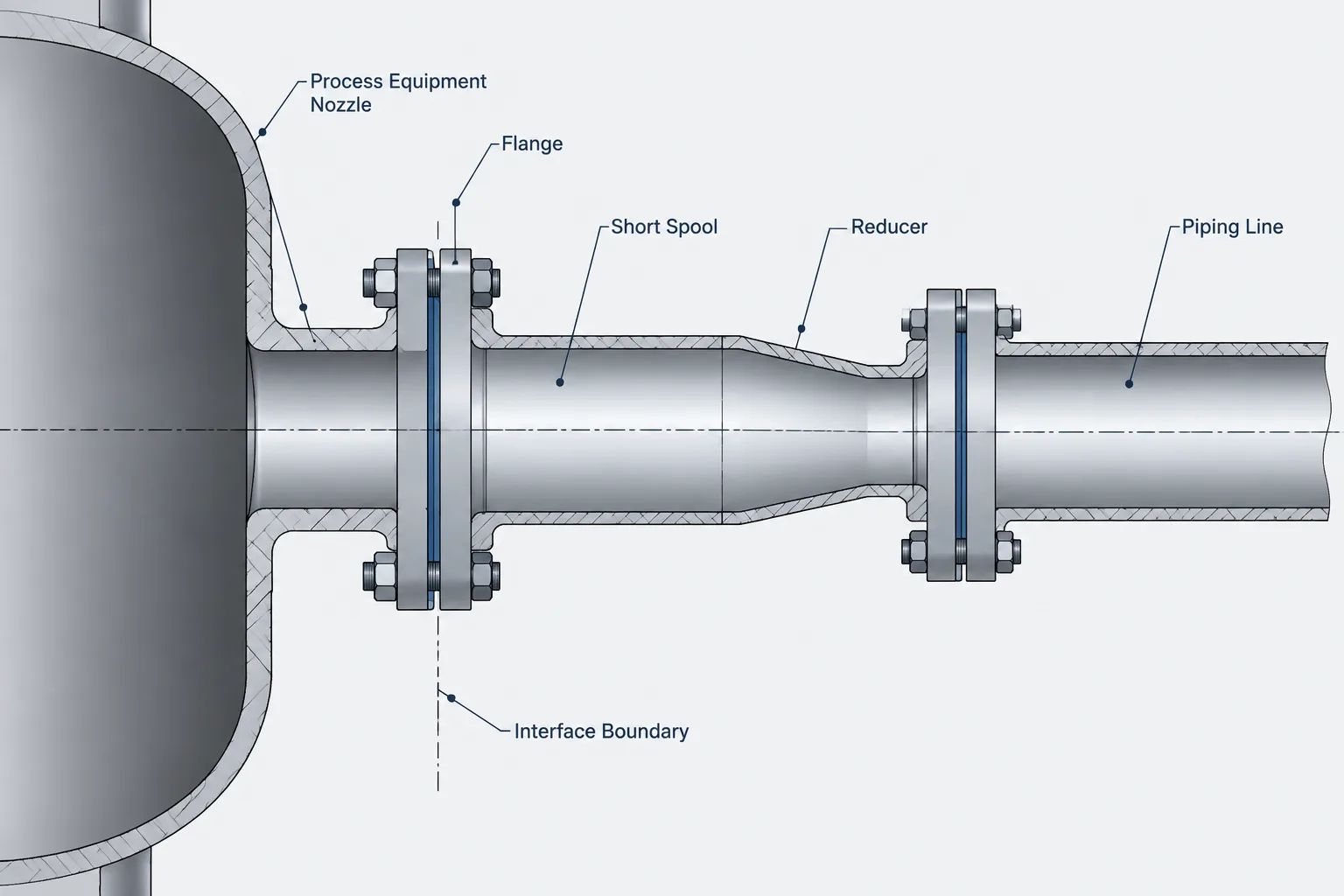
  • Equipment Nozzle Size Mismatches in Piping CAD: Reducers, Flanges, and Interface Control

    Equipment Nozzle Size Mismatches in Piping CAD: Reducers, Flanges, and Interface Control

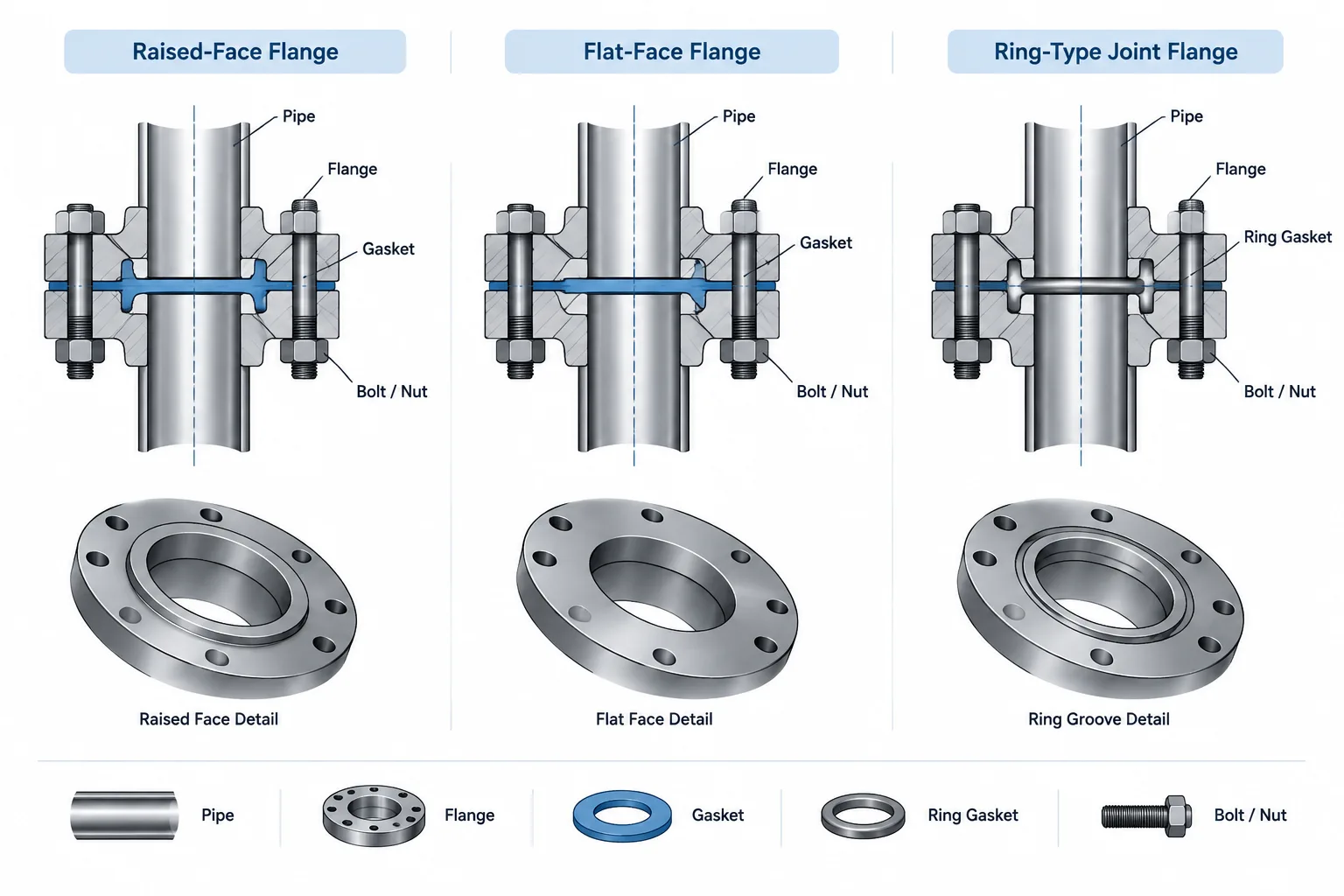
  • Flange Face Types in Piping CAD: Raised Face, Flat Face, and Ring-Type Joint

    Flange Face Types in Piping CAD: Raised Face, Flat Face, and Ring-Type Joint

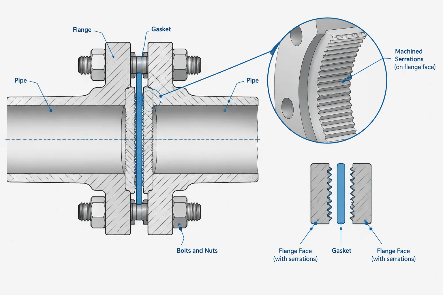
  • Flange Facing Finish in Piping Drawings: Serrations, Roughness, and Gasket Compatibility

    Flange Facing Finish in Piping Drawings: Serrations, Roughness, and Gasket Compatibility

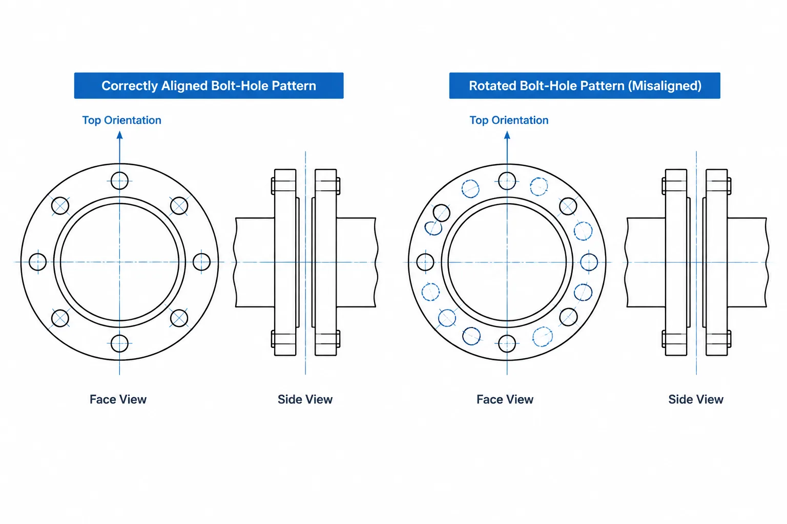
  • Flange Bolt-Hole Orientation in CAD: Straddling Centerlines, Clocking, and Face Views

    Flange Bolt-Hole Orientation in CAD: Straddling Centerlines, Clocking, and Face Views

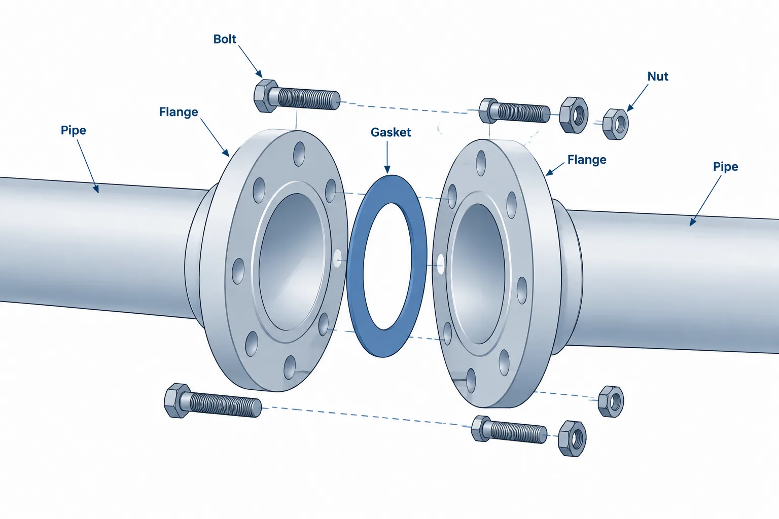
  • Piping Gaskets in CAD: How to Model, Specify, and Check Flanged-Joint Seals

    Piping Gaskets in CAD: How to Model, Specify, and Check Flanged-Joint Seals

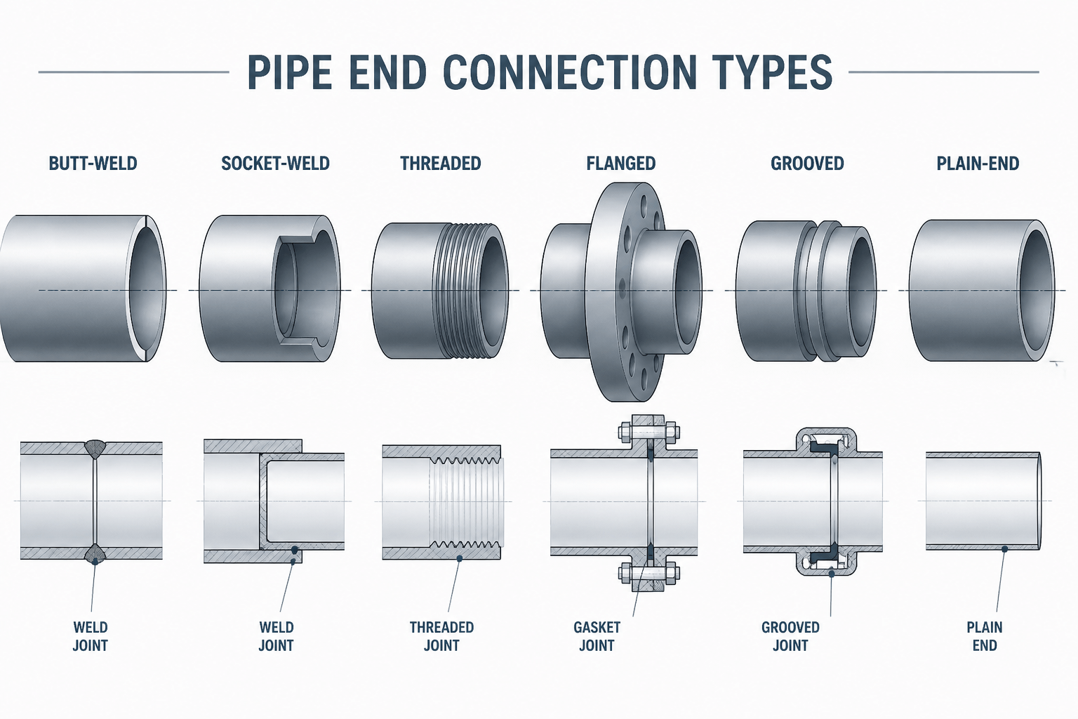
  • Pipe End Connection Types: How to Read and Detail Them in CAD

    Pipe End Connection Types: How to Read and Detail Them in CAD