Determining flange bolt length in CAD is an assembly-control task, not simply a flange lookup. The model must represent the actual connection, including the sealing element, intermediate components, external hardware, fastener style, and required engagement or projection.
This guide explains how to organize that information into a reviewable stack-up while keeping verified dimensional data separate from CAD calculation logic. The objective is a traceable result that agrees with the connection detail, material specification, bill of materials, and approved purchasing practice.
Flange bolt length can look like a simple catalog value, but the correct fastener depends on the entire joint rather than the flanges alone. Gaskets, washers, insulating components, valve bodies, tapped holes, and project-specific protrusion rules can all change the required length. A CAD model that shows only two mating flanges may therefore be insufficient for purchasing or fabrication.
The safest drafting approach is to treat bolt length as a controlled result of the joint stack-up. Verified flange and fastener tables provide the authoritative dimensions; the CAD workflow establishes which dimensions belong in the calculation and whether the modeled assembly matches the bill of materials.
What flange bolt length represents
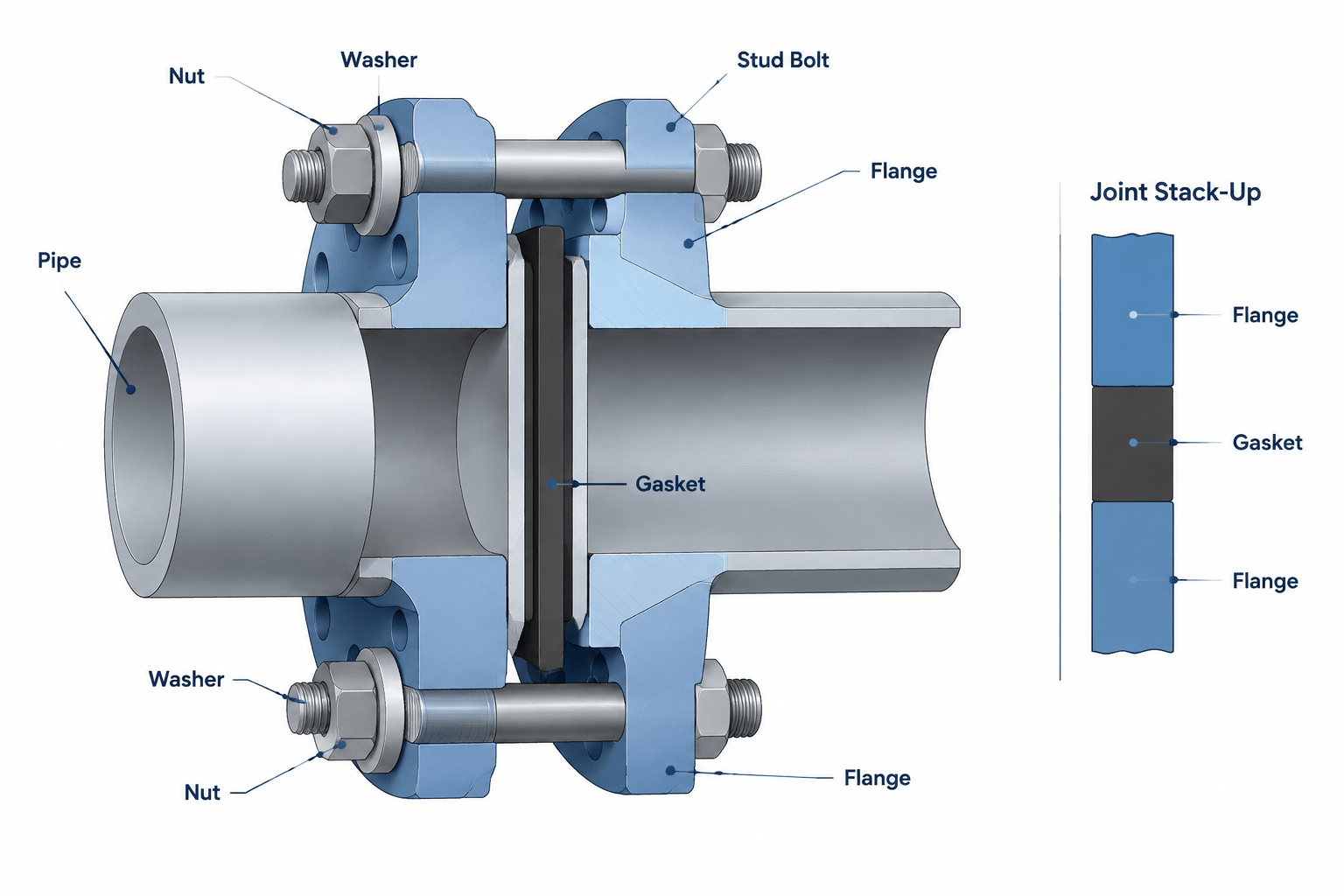
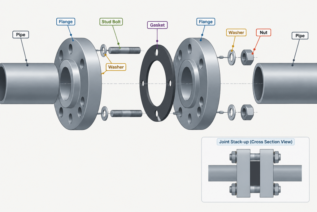
For a conventional through-bolted flange joint, bolt length must accommodate the parts captured between the nuts and leave enough threaded engagement for assembly. A typical stack may include:
- The bolting thickness of the first flange
- The gasket or sealing element
- The bolting thickness of the second flange
- Washers, when required by the project specification
- Insulating sleeves and washers, when an isolation kit is used
- Nuts and the required thread projection
This stack is not always symmetrical. A flanged valve may have different end geometry from a separate pipe flange. A lap-joint assembly introduces backing flanges and stub ends. A spectacle blind or spacer adds another component between the flange faces. Each configuration needs to be identified before a bolt length is assigned.
Stud bolts, machine bolts, and cap screws are not interchangeable
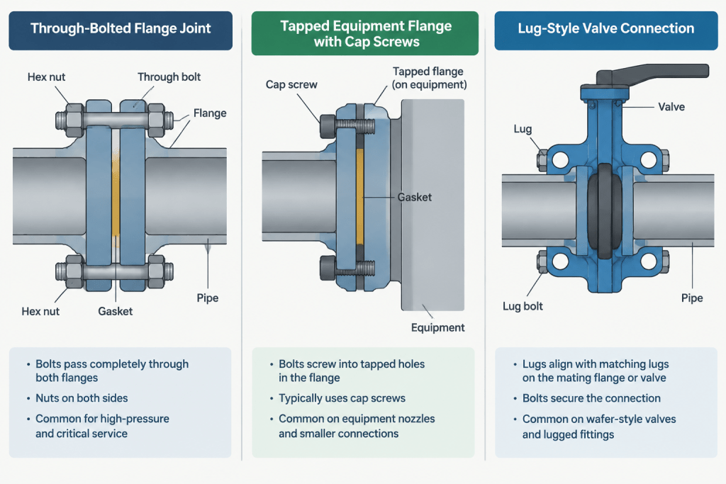
The fastener type determines how length is interpreted. For a stud bolt with nuts at both ends, the stated length generally relates to the overall stud, but the exact measurement convention must be confirmed from the governing fastener reference or supplier documentation. For a headed machine bolt, length is commonly associated with the distance from the bearing surface beneath the head to the end of the bolt. A cap screw entering a tapped component requires a different check because there may be no nut on the far side.
CAD libraries should not use one generic “bolt length” property for every fastener without also recording fastener type. Otherwise, two parts with the same length value may represent different physical measurement bases.
Build the flange joint as a stack-up
Start with the actual mating components
Identify both sides of the connection by component type, nominal size, pressure class, facing, and material specification. Do not assume that two components with matching connection descriptions have identical bolting thicknesses. Use the site’s verified dimensional pages or approved vendor data for each component.
Identify everything between the flange faces
The space between flanges is not always occupied by a standard gasket alone. The joint may contain a blind, spacer, orifice component, strainer plate, proprietary seal, or insulating gasket. These items affect both the flange separation and the fastener stack.
Use the thickness basis specified for assembly calculations. Nominal supplied thickness and installed thickness are not necessarily the same concept, particularly for compressible sealing materials. CAD should not invent a compressed value. If the required basis is unclear, flag it for engineering or vendor confirmation.
Add external hardware deliberately
Washers are often omitted from simplified models, but they affect grip length. Record whether washers are used under nuts, under bolt heads, on both ends, or as part of an insulating kit. Do not add them solely because a generic CAD block includes them.
Nuts also require a defined dimensional source. Heavy-pattern and standard-pattern nuts, for example, should not be treated as geometrically identical. When a joint has different hardware on opposite ends, calculate each side rather than assuming symmetry.
Apply the project’s thread projection rule
Thread projection is the portion of the fastener extending beyond the assembled nut. It provides visible confirmation of engagement and may support installation practices, but the required amount is a project or governing-document decision. Avoid embedding an unexplained fixed projection in a CAD formula.
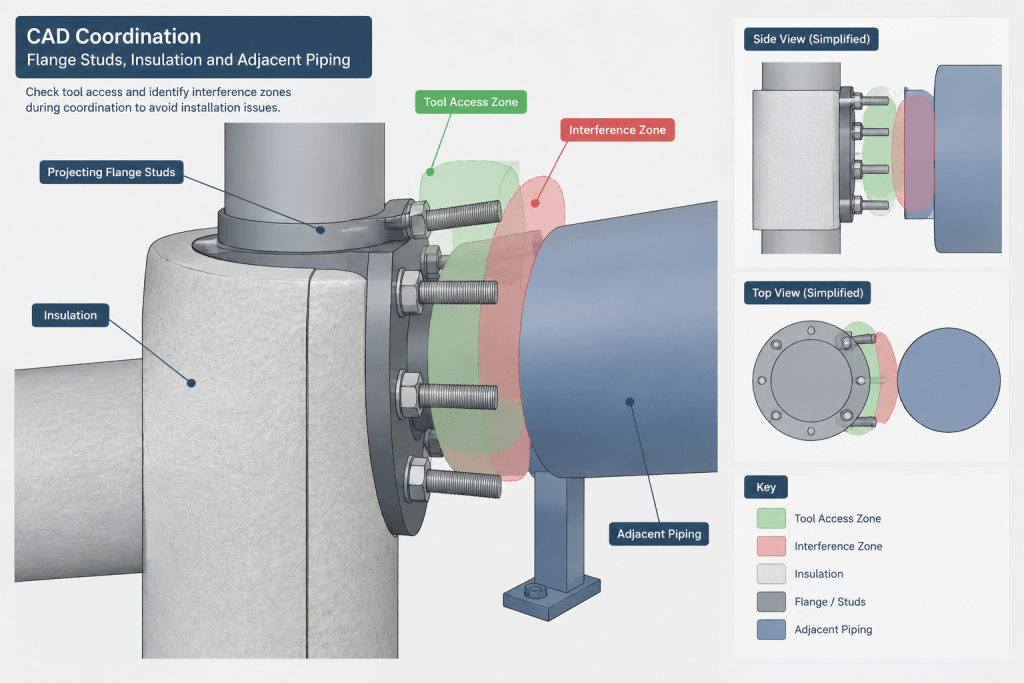
Projection should be considered at both ends of a stud. Excessive length can also create problems by interfering with nearby piping, insulation, equipment, tools, or removable covers. A bolt that is long enough is not automatically well coordinated.
A practical stack-up worksheet
A worksheet makes the bolt-length decision traceable without replacing the authoritative dimension tables. Suggested fields include:
| Stack item | Source to verify | CAD or review note |
|---|---|---|
| First flange bolting thickness | Verified flange data or approved component drawing | Confirm facing and flange type |
| Intermediate components | Gasket, blind, spacer, or vendor data | State the thickness basis used |
| Second flange or equipment connection | Verified data or vendor drawing | Do not assume it matches the first side |
| Washers and insulating hardware | Project specification or kit supplier | Record quantity and location |
| Nuts or threaded engagement | Approved fastener data | Distinguish through-bolting from tapped holes |
| Thread projection | Project bolting practice | Check nearby clearance |
| Selected purchase length | Approved available-length series | Document the rounding method |
The arithmetic stack-up produces a required minimum based on the selected assumptions. The procurement length may then need to be selected from available increments. Rounding direction and acceptable projection should follow the project bolting practice rather than an informal drafting preference.
Connections that need special treatment
Tapped flanges and equipment bodies
Some valves, equipment nozzles, and specialty components use tapped holes. The fastener must provide sufficient thread engagement without bottoming in the hole or contacting an internal obstruction. A through-bolt stack-up does not resolve this condition. Use the approved vendor drawing to establish hole depth, usable thread depth, and permitted fastener type.
Wafer and lug-style components
A wafer component is captured between mating flanges, so its face-to-face dimension becomes part of the grip. A lug-style component may use separate cap screws entering tapped lugs from each side. These arrangements can appear similar in a low-detail model while requiring entirely different bolting.
The CAD object should identify the connection pattern, not merely show a generic valve body between flanges.
Insulating flange kits
Electrical isolation kits may add insulating gaskets, sleeves, washers, and backing washers. They also influence bolt diameter clearances and the order in which hardware is assembled. Model or annotate the complete kit where coordination matters, and avoid deriving its dimensions from a visual approximation.
Blinds, spacers, and line blinds
Inserting a blind or spacer changes the joint thickness. A line blind may also need clearance for rotation or removal. If the operating position can change, confirm whether one bolting arrangement works for all intended positions or whether separate hardware is required.
How much detail belongs in the CAD model?
Not every model needs helical threads, individual washers, or fully detailed nuts. The level of detail should support the deliverable:
- Layout model: Represent the bolt envelope when it affects access, insulation, or nearby equipment.
- Fabrication model: Associate the connection with verified fastener diameter, quantity, type, and length data.
- Isometric: Show the joint components and include bolting information through the project’s material callout system.
- Detail drawing: Illustrate hardware order when specialty washers, isolation parts, or tapped connections could be assembled incorrectly.
Even when fasteners are not modeled individually, the database record should distinguish a calculated value from an approved purchasing value. This prevents an early layout assumption from silently becoming a material order.
Common flange bolt length errors
- Using a standard two-flange table for a valve, blind, or specialty joint
- Applying one flange thickness twice when the mating components differ
- Omitting washers or insulating hardware from the grip
- Mixing stud-bolt and headed-bolt length conventions
- Using nominal gasket thickness without confirming the required calculation basis
- Rounding to an available length without checking resulting projection
- Ignoring interference between projecting studs and adjacent objects
- Calculating cap screws as though they were through-bolts with nuts
- Copying bolting from a visually similar connection with a different class, facing, or component type
CAD review checklist
- Are both mating components correctly identified?
- Does the modeled connection match the line or piping material specification?
- Are all items in the flange-face stack included?
- Is the fastener type defined along with its length?
- Are nut and washer types taken from approved project data?
- Has thread projection been checked at each exposed end?
- For tapped holes, has usable engagement been verified from vendor information?
- Does the selected purchase length follow the approved available-length series?
- Is there room to install, tighten, and remove the fastener?
- Do the model, isometric, and bill of materials report the same bolting arrangement?
Keep reference data separate from assembly logic
Reference pages answer questions such as flange thickness, bolt diameter, hole count, and standard fastener dimensions. The CAD assembly answers a different question: which verified values apply to this particular joint?
Keeping those roles separate improves revision control. When a flange, gasket, valve, or insulating kit changes, the designer can rebuild the stack-up from controlled inputs instead of editing an unexplained bolt-length value. The result is a clearer connection detail, a more reliable material list, and a joint that can be reviewed before hardware reaches the field.
Turn the stack-up into controlled CAD data
A useful CAD workflow separates component inputs from the resulting fastener selection. Flange geometry, gasket information, washer arrangement, nut type, and vendor-defined connection details should remain identifiable inputs rather than being absorbed into an unexplained bolt-length attribute.
Distinguish the calculation stages
- Joint definition: Identifies the components and hardware that physically form the connection.
- Calculated requirement: Records the length produced by the verified stack-up assumptions.
- Selected purchase length: Records the approved available fastener chosen under project rules.
- Released material data: Identifies the value authorized for drawings, schedules, and procurement.
Keeping these stages distinct makes changes easier to audit. If a gasket, valve, blind, washer arrangement, or flange type changes, the reviewer can identify which input affected the result and determine whether the purchasing selection must also change.
Use status fields instead of silent assumptions
A connection record can indicate whether its bolting is preliminary, calculated, vendor-dependent, reviewed, or released. This is especially helpful when equipment information is incomplete or when tapped-hole details have not yet been confirmed. An unresolved value should remain visibly unresolved rather than being presented as approved material data.
Coordinate geometry with material reporting
The modeled fastener envelope and the reported fastener description serve different purposes, but they must refer to the same assembly. Geometry supports access and interference review, while the material record controls type, length, and associated hardware. A revision check should compare both so that a visually acceptable model does not conceal an outdated bill-of-material entry.
Frequently asked questions
Can flange bolt length be taken directly from a flange table?
Only when the table applies to the complete joint configuration and the project accepts its stated assumptions. A table for mating flanges may not account for valves, blinds, spacers, insulating kits, specialty seals, washers, or tapped connections.
Should gasket thickness be measured from the CAD model?
No. The thickness basis should come from approved gasket data and the project’s assembly method. A simplified model is useful for coordination, but it should not create an assumed installed thickness for a compressible sealing element.
Why must the CAD record identify the fastener type?
Stud bolts, headed bolts, and cap screws do not share the same assembly arrangement or length interpretation. Recording only a generic length can cause the model, drawing, and purchasing description to refer to different physical fasteners.
How should a tapped connection be checked?
Use approved component or vendor information to verify usable thread depth, required engagement, possible bottoming, and internal obstructions. A conventional flange stack-up with a nut on the opposite side does not represent this condition.
Does a longer bolt always provide a safer selection?
No. Additional projection may interfere with tools, insulation, adjacent piping, equipment, or removable parts. The selected length must satisfy engagement requirements while remaining compatible with the project’s projection and clearance rules.
What should happen when vendor connection data is unavailable?
Mark the bolting selection as unresolved or preliminary and identify the missing input. Avoid releasing a purchasing length based on visual scaling, a similar-looking component, or an assumed tapped-hole condition.