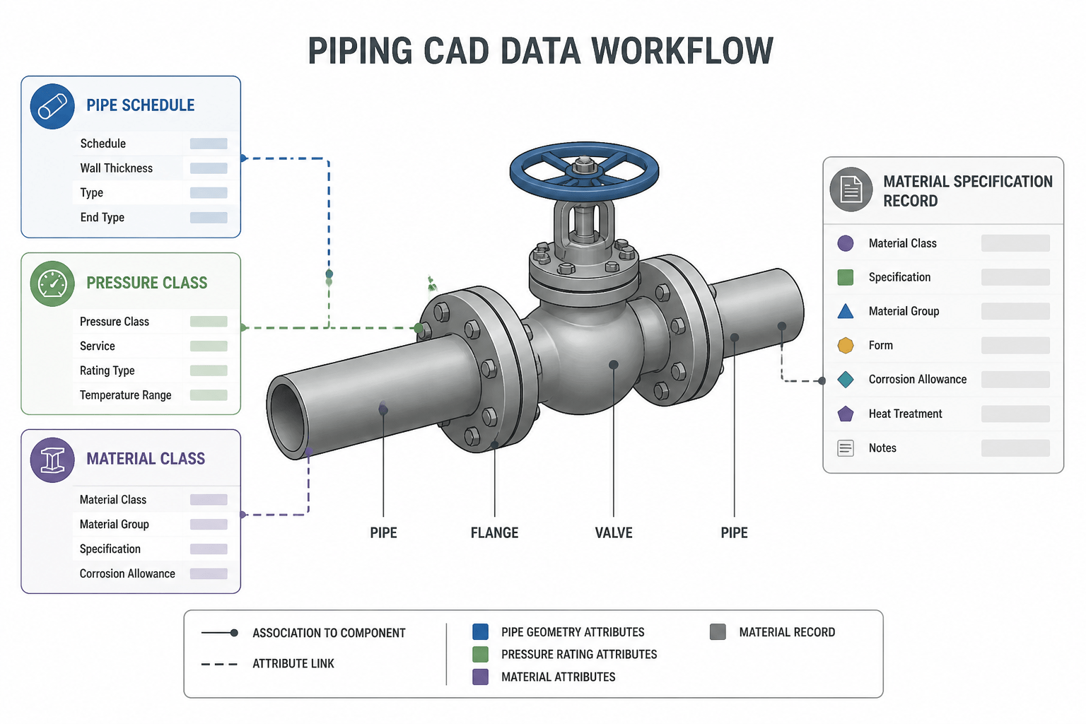
Reliable piping CAD depends on keeping related attributes separate and traceable. Pipe schedule, pressure class, and material class may appear in the same specification or component description, but each answers a different data question.
This guide explains how to distinguish these terms, connect them through a controlled CAD workflow, and review the resulting model, drawings, and material takeoffs without treating visual similarity as proof of technical compatibility.
Pipe schedule, pressure class, and material class often appear together in piping design data, but they describe different things. Treating them as interchangeable can produce confusing specifications, incorrect component selections, and drawings that are difficult to review.
In CAD, these terms should be connected through a controlled piping specification or line-data workflow. The drawing may show only a portion of the information, while the model, bill of materials, line list, and component database carry the rest. A clear understanding of each term helps drafters identify missing data and prevents a visual representation from being mistaken for an engineering approval.
What pipe schedule describes
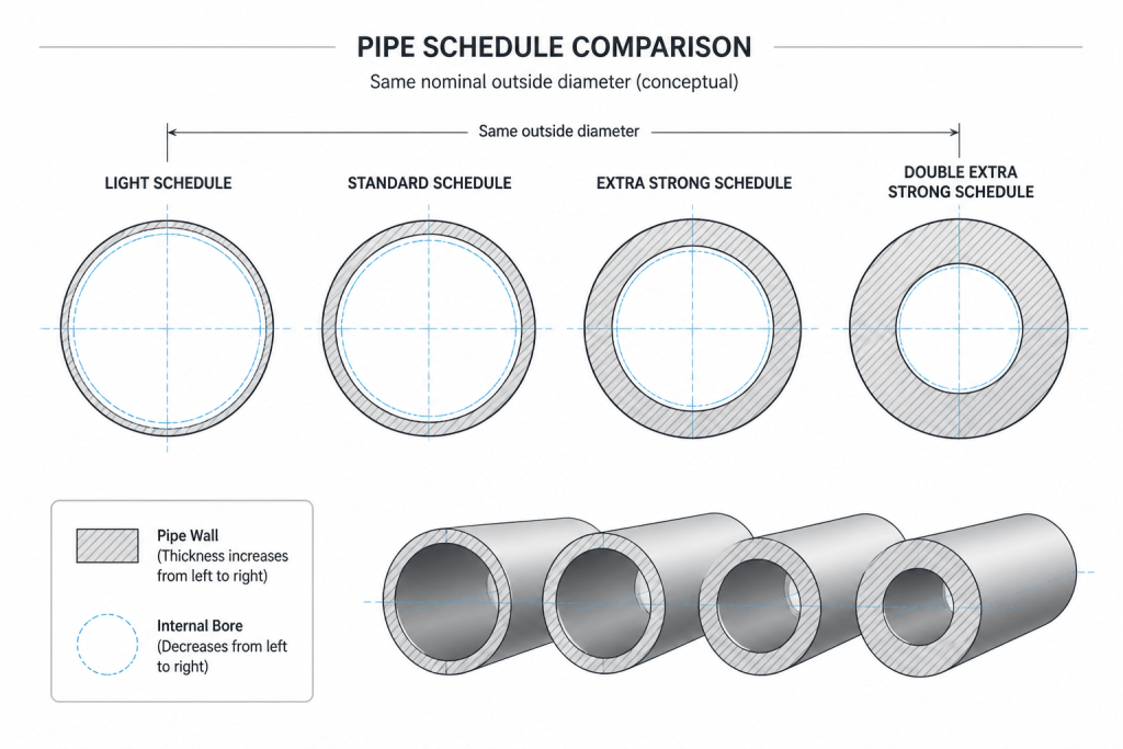
Pipe schedule is a designation associated primarily with pipe wall thickness. It is used to identify a particular wall-thickness series for a given nominal pipe size. The actual outside diameter commonly remains associated with the nominal size system, while the inside diameter changes as the wall becomes thicker or thinner.
That distinction matters in CAD. A pipe drawn with the correct nominal outside diameter can still have the wrong internal bore if its schedule is wrong. The visual difference may be difficult to notice in a small-scale plan or isometric, especially when the pipe is represented by a centerline and a nominal size label.
Schedule information can affect:
- the modeled pipe wall and displayed section profile;
- the calculated or tabulated inside diameter;
- the connection detail at fittings, valves, and branches;
- the material description in a bill of materials;
- weight and support-related engineering data supplied by the project;
- fabrication or procurement identification.
A schedule designation should therefore be read from the applicable project specification or verified dimension database. It should not be inferred from the line appearance alone.
What pressure class describes
Pressure class is a designation used for certain piping components, especially flanges, valves, and other pressure-containing items. It identifies a standardized or project-controlled pressure-temperature capability category for that component family. It is not simply another name for pipe wall thickness.
A flange pressure class, for example, helps identify the corresponding flange geometry, bolting arrangement, facing details, and pressure-temperature limitations defined by the applicable design basis. A valve may carry a pressure class designation that relates to its body, ends, trim, and operating limitations. These details must be checked against the component data rather than assumed from a nearby pipe schedule.
In CAD, pressure class may control:
- which flange or valve family is selected from the component library;
- the end-to-end or face-to-face dimension used in routing;
- the flange outside diameter and bolt-hole arrangement shown in detail;
- the connection compatibility between adjoining components;
- the description and identification recorded in the material takeoff.
A pressure class does not automatically define the pipe wall thickness. The pipe, flange, valve, gasket, bolts, and other components must be selected as a compatible set under the project specification and applicable design basis.
What material class or piping class describes
Material class, piping class, or piping material specification is a broader project control category. Terminology varies between companies, but the purpose is generally to group the permitted materials, components, joining methods, ratings, corrosion allowances, end connections, and service restrictions for a defined piping service or design area.
A material class may identify the required pipe material and schedule, but it can also control much more. Depending on the project, it may govern the permitted elbows, tees, reducers, flanges, valves, gaskets, bolting, branch connections, coatings, insulation interfaces, and special fabrication requirements.
This is why a line number or nominal size is not enough to select a component. Two lines with the same nominal size may use different material classes and therefore require different pipe walls, flange types, valve materials, gasket families, or joining details.
| Term | Primary purpose | Typical CAD or document effect |
|---|---|---|
| Pipe schedule | Identifies a pipe wall-thickness series | Pipe section, bore, material description, and takeoff data |
| Pressure class | Identifies a component pressure-temperature category | Flange, valve, bolting, facing, and component geometry |
| Material class | Groups the permitted piping materials and components | Component selection, specification rules, and line-level consistency |
Why these terms are easy to confuse
The terms are often displayed in compact tags. A line designation may contain a nominal size, service code, material-class identifier, insulation code, and testing information in one string. A component description may then include a nominal size, schedule reference, pressure class, material, and end connection.
Because the information is compressed, a drafter may mistake one field for another. A pressure-class value may be read as a pipe rating. A schedule may be copied from an adjacent line without checking the specification. A valve may be inserted from a library family that has the right nominal size but the wrong pressure class or end connection.
The safest approach is to treat each value as a separate attribute and verify the relationship between them. Do not use a single label as a substitute for the full component identity.
How to apply the information in a CAD workflow
1. Start with the line-level inputs
Before modeling, identify the line number, nominal size, service, design inputs supplied by the project, material class, insulation status, and any special restrictions. The line list, P&ID, piping material specification, and project modeling rules may each provide different parts of this information.
Resolve conflicts before placing components. A line number alone should not be used to guess a schedule or pressure class.
2. Load the piping specification into the component workflow
Use the project-approved specification or database to filter available pipe, fittings, flanges, valves, and branch components. The goal is to make incompatible selections difficult to place, not merely to rely on a final visual review.
Where the CAD system does not enforce specification rules, use a documented manual check. Record the selected schedule, material, pressure class, end connection, and component type in a model property set or review worksheet.
3. Check connection compatibility
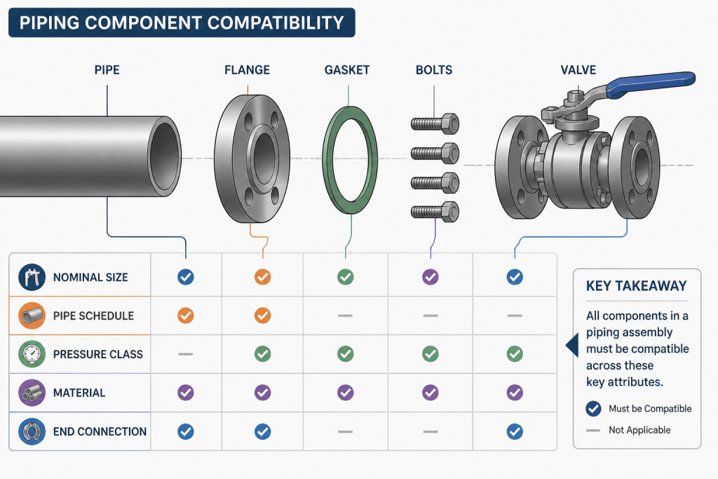
At every transition, compare more than nominal size. Check the pipe wall or schedule, component pressure class, flange facing or end connection, material requirements, and the intended joining method. A component can look geometrically correct while still being wrong for the line specification.
Pay particular attention to reducers, branch connections, valve ends, spectacle blinds, flanges, and equipment nozzles. These are common points where data from different specifications can be combined incorrectly.
4. Verify the drawing representation
Make sure the isometric, plan, section, and bill of materials present the same component identity. The drawing may use abbreviated annotations, but the abbreviation should map unambiguously to the model and material description.
Check that the pipe schedule is not omitted where it is required for identification, and that pressure class is shown or encoded for components where it affects procurement or connection review. If the project uses a specification code instead of displaying every property, ensure the code is correct and traceable to the current project data.
A practical review checklist
- Is the pipe schedule taken from the correct material class rather than copied from a neighboring line?
- Does the component pressure class match the governing piping specification?
- Are flange, valve, gasket, and bolting selections treated as a compatible group?
- Do pipe ends and component ends use compatible connection types?
- Do branches and reducers reflect the correct wall or component requirements?
- Does the model property data agree with the isometric annotation and bill of materials?
- Are specification breaks clearly identified where the governing material class changes?
- Have unresolved data assumptions been recorded for engineering review?
Use reference tables without losing the design context
Dimension and schedule tables are valuable for confirming pipe dimensions and component geometry, but they do not replace the project specification. A table can help verify a nominal outside diameter, wall designation, flange dimension, or fitting takeout. It cannot, by itself, determine whether that item is permitted for a particular service or line.
Use the reference data to validate the CAD representation, then use the piping specification and approved project inputs to validate selection. Keeping those roles separate makes the drawing more reliable and makes later reviews easier to audit.
Final takeaway
Pipe schedule describes a pipe wall-thickness series. Pressure class identifies a component pressure-temperature category. Material class organizes the approved piping materials and components for a service or project application. They work together, but none of them should be used as a replacement for the others.
When these attributes are stored separately, checked at connections, and carried consistently into the model, drawings, and material takeoffs, CAD teams can catch specification errors before they become fabrication or procurement problems.
Think in terms of data ownership
A useful way to review piping information is to ask which source owns each attribute. The piping specification typically governs permitted combinations, the component database supplies selectable geometry and descriptions, and the CAD model carries the selected properties into drawings and takeoffs.
When a value is missing or inconsistent, avoid correcting it by appearance alone. Trace it back to the governing line data, specification, approved component record, or project instruction. This creates a reviewable decision path and reduces the risk of silently copying an adjacent component’s information.
Use a deliberate discrepancy review
When the model, drawing, and bill of materials disagree, compare the component identity as a group rather than checking one label in isolation. Review nominal size, pipe schedule where applicable, pressure class where applicable, material class, end connection, and component type together. Then determine whether the discrepancy comes from a modeling selection, an annotation rule, a database description, or a specification change.
Record unresolved conflicts for the responsible engineering or project authority. A drafting correction should not be used to make an uncertain selection appear approved.
Separate visual validation from specification validation
CAD review serves two related but different purposes. Visual validation checks routing, connectivity, representation, and drawing readability. Specification validation checks whether the selected components and attributes are permitted and mutually compatible. Both reviews are needed because a component can look correct in an isometric while carrying an incorrect specification identity.
This distinction is especially important when abbreviated tags, shared libraries, or automated material takeoffs are used. Clear property mapping helps reviewers move from a drawing label to the underlying model data and then to the governing project requirement.
Frequently asked questions
Is pipe schedule the same as pressure class?
No. Pipe schedule identifies a pipe wall-thickness series, while pressure class identifies a pressure-temperature category for applicable components. They should be checked separately.
Does pressure class determine pipe wall thickness?
No. Pressure class does not automatically define the pipe wall thickness. Pipe selection and component selection must be coordinated through the applicable specification and design basis.
What does a material class control in CAD?
A material class generally groups the permitted piping materials and components for a defined service or project area. Depending on the project, it may influence pipe, fittings, flanges, valves, joining methods, and related restrictions.
Can a drafter determine the schedule from the drawing?
Not reliably. A drawing representation may omit wall information or use a nominal-size label. The schedule should be taken from the applicable project data or verified dimension and specification resources.
Why should component attributes be stored separately?
Separate attributes make it easier to filter components, check connection compatibility, compare model and drawing data, and identify which value is missing or inconsistent.
What should be done when CAD data conflicts with the piping specification?
Pause the affected selection or review, trace both values to their sources, and record the conflict for resolution by the responsible project or engineering authority. Do not rely on visual similarity to choose between them.