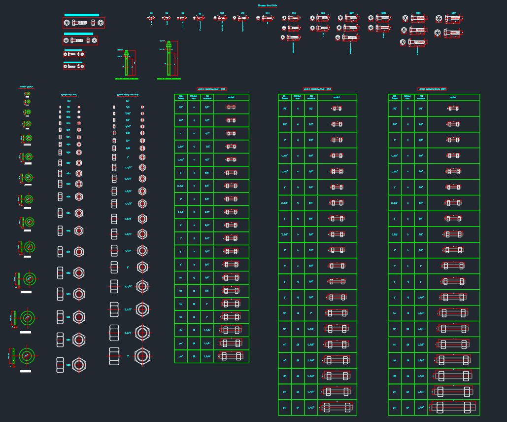
The Bolt and Nut CAD Blocks DWG resource provides reusable fastener details for engineers, designers, detailers, and CAD professionals. It is intended to support clear drafting of bolt, nut, washer, and threaded-fastener representations in mechanical, structural, fabrication, and workshop documentation.
Use the drawing as a drafting reference rather than as a substitute for project specifications. Fastener selection, connection design, material requirements, installation requirements, and final dimensions must be checked against the applicable project documents and engineering requirements.
The Bolt and Nut CAD Blocks DWG file is a useful technical resource for engineers, mechanical designers, steel detailers, and CAD professionals who need accurate fastener drawings for fabrication and assembly work. This CAD drawing includes a variety of bolt, nut, and fastener details in multiple views and standard size references, making it suitable for workshop drawings, mechanical design, structural detailing, and manufacturing documentation.
This type of CAD block library is commonly used in steel structure drawings, machine assembly details, fabrication layouts, equipment design, and connection detailing. The drawing may include hex bolts, nuts, washers, threaded fasteners, side views, front views, sectional representations, and dimension-based size tables to support clear drafting and standardization in technical projects.
Using a well-organized bolt and nut CAD block library helps improve drafting speed, drawing consistency, and accuracy when preparing technical details. It is especially useful for professionals working on mechanical components, structural steel connections, industrial equipment, machine parts, and workshop production drawings. The included size charts and detail layouts also make it easier to select the right fastener representation for different engineering applications.
Whether you are creating fabrication drawings, updating a mechanical CAD library, or preparing standard connection details, this Bolt and Nut CAD Blocks DWG file is a practical addition to your design resources. It supports efficient drafting and clearer technical communication across engineering and manufacturing projects.
How to use the fastener CAD drawing
Fastener blocks are most useful when a drawing needs a consistent visual representation without redrawing common components. The supplied DWG includes bolt and nut details, multiple views, sectional representations, and dimension-based size references described in the source content. These elements can help users prepare connection details, assembly drawings, fabrication layouts, and equipment documentation.
What to check before inserting a block
- Confirm the drawing units, insertion scale, orientation, and base point in the CAD environment.
- Review whether the selected view communicates the intended assembly condition, such as a side, front, or sectional view.
- Match the fastener representation to the project’s required size, thread convention, washer arrangement, and connection notes.
- Keep drawing dimensions and callouts coordinated with the approved design information; do not infer a fastener specification from appearance alone.
- Check layer names, linework, text styles, and plotting behavior before adding the block to a production drawing.
Related drafting references
This resource can be used alongside PipeSTD references for flange details, pipe fittings, pipe dimensions and schedules, and CAD/DWG drafting resources. Linking these subjects helps users move from a fastener detail to the surrounding piping, equipment, or structural connection documentation.
Drafting value and engineering limits
A well-organized CAD block library improves consistency and reduces repetitive drafting work. It does not, by itself, establish bolt capacity, tightening requirements, material grade, corrosion protection, or connection adequacy. Those decisions require the governing project specification and verification by the responsible engineer or detailer.
Frequently asked questions
What is included in the Bolt and Nut CAD Blocks DWG?
The source describes a collection of bolt, nut, washer, and threaded-fastener details with multiple drawing views, sectional representations, and size references.
Who can use this DWG resource?
It is useful for mechanical designers, structural steel detailers, engineers, fabricators, and CAD professionals preparing technical drawings and connection details.
Can the blocks be used directly for fabrication?
The blocks can support fabrication and assembly documentation, but the user must verify units, dimensions, fastener identification, project notes, and approved design information before issuing a drawing.
Does the CAD block determine the correct fastener?
No. A graphical block represents a drafting detail. The correct fastener depends on the project specification, connection requirements, materials, installation conditions, and engineering verification.