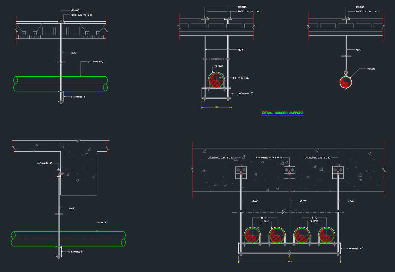
Pipe hanger support details provide a clear drafting reference for showing how suspended piping is arranged, connected, and coordinated with the building or plant structure. This resource is intended for engineers, HVAC and plumbing designers, MEP coordinators, and CAD drafters who need a practical pipe support drawing for project documentation.
Use the DWG as a starting point for mechanical details, ceiling service layouts, piping support plans, and fabrication references. Always compare the selected arrangement with the project specifications, structural conditions, piping loads, required movement, and applicable engineering review before issuing it for construction.
The Pipe Hanger Support Details CAD Drawing is a practical resource for mechanical engineers, HVAC designers, MEP drafters, and plumbing professionals who need accurate support details for suspended piping systems. This drawing includes several pipe hanger and support configurations, showing how pipes can be safely suspended from structural slabs, beams, or ceiling supports in technical construction drawings.
This CAD file is useful for HVAC piping layouts, plumbing systems, fire protection installations, industrial piping networks, and mechanical service coordination. It typically includes different support methods such as single pipe hangers, U-bolt supports, channel supports, rod hangers, and multiple pipe support arrangements. These details help designers clearly define support spacing, fixing methods, and connection components in project drawings.
Using a detailed pipe hanger support CAD block improves drawing quality, installation clarity, and coordination between design and construction teams. It is especially useful when preparing mechanical detail drawings, ceiling service layouts, piping support plans, and fabrication references. The drawing also helps ensure that suspended piping systems are represented in a consistent and professional format.
Whether you are working on commercial buildings, industrial plants, utility rooms, or MEP coordination drawings, this Pipe Hanger Support Details DWG file is a valuable addition to your CAD library. It supports faster drafting, better project documentation, and more efficient piping design workflows.
How to read the pipe hanger support drawing
The details illustrate several ways to represent suspended piping, including single pipe hangers, U-bolt supports, channel supports, rod hangers, and multiple pipe support arrangements. Each configuration helps communicate the relationship between the pipe, its supporting member, and the connection to a slab, beam, or ceiling support.
What to check during coordination
- Support arrangement: Confirm that the selected detail matches the number of pipes and the intended installation condition.
- Connection method: Review how the hanger or support is shown attaching to the supporting structure and identify any project-specific fixing requirements.
- Pipe interface: Check the contact and restraint condition around the pipe, including whether the detail represents suspension, guidance, or a more fixed support condition.
- Clearance and access: Coordinate the support with nearby ducts, cable trays, valves, insulation, ceilings, and maintenance routes.
- Drawing consistency: Keep support symbols, callouts, notes, and references consistent across plans, sections, details, and fabrication documents.
Support spacing should be established from the applicable project requirements and the properties of the piping system rather than copied automatically from a generic CAD block. The designer should also consider operating conditions, filled-pipe weight, thermal movement, vibration, seismic requirements where applicable, and the capacity of the supporting structure. These checks help turn a drafting reference into a coordinated engineering detail.
Using the DWG in a CAD workflow
Insert the selected detail into the project template, then revise layer standards, linework, annotations, and material or component descriptions to match the drawing set. Link the detail to the relevant piping plans and sections so installers can understand its location and intended use. Related references on pipe dimensions and schedules, fittings, flanges, and piping terminology can help verify the surrounding design information before the support detail is finalized.
Frequently asked questions
What is included in a pipe hanger support detail?
A pipe hanger support detail typically shows the pipe support configuration, the supporting member, the connection concept, and the way the pipe is suspended or carried. The supplied drawing includes single-pipe, U-bolt, channel, rod-hanger, and multiple-pipe arrangements.
Where can this pipe support DWG be used?
The file can support HVAC piping layouts, plumbing systems, fire protection installations, industrial piping networks, mechanical service coordination, and related construction documentation. Its suitability for a particular project must be confirmed by the responsible design team.
Does the drawing determine support spacing?
No. The drawing helps communicate support methods and coordination intent, but actual spacing must be established from the project design basis, piping system requirements, structural conditions, and applicable review criteria.
Can a generic hanger detail be issued directly for construction?
A generic CAD detail should be adapted and checked before issue. Verify dimensions and notes shown in the project version, connection requirements, clearances, loads, movement conditions, and coordination with the structural and MEP drawings.
Who benefits from this CAD reference?
Mechanical engineers, HVAC designers, plumbing professionals, MEP drafters, fabricators, and coordination teams can use the detail as a common visual reference when developing suspended piping documentation.