Flange isolation kits require coordination between piping design, corrosion control, materials, CAD administration, procurement, and field installation. A model may show a familiar bolted flange pair, yet the joint has a specialized electrical-isolation function that can be lost when component properties, bolting, or material quantities are handled as standard items.
This guide explains how to preserve that function in piping CAD without substituting assumed dimensions for approved project or supplier data. It focuses on assembly identification, joint stack-up, model detail, material records, drawing communication, and practical design review.
A flange isolation kit is used where a bolted piping joint must provide electrical separation between connected components. It may support corrosion-control strategies, separate dissimilar metallic systems, or define a boundary associated with cathodic protection. Although it can resemble an ordinary flanged joint in a general arrangement drawing, its gasket and bolting arrangement requires additional attention in detailed CAD models, isometrics, and bills of material.
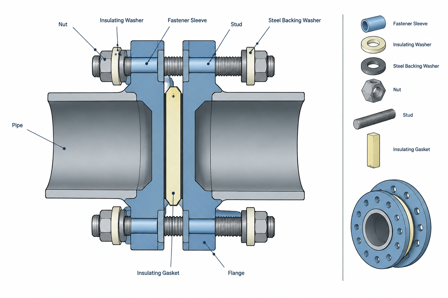
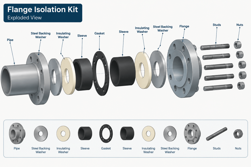
The designer should not treat an isolation kit as a generic gasket note. The assembly can include an insulating gasket, sleeves around the fasteners, insulating washers, and steel backing washers. The exact configuration depends on the selected kit, flange geometry, service conditions, project specification, and supplier documentation. CAD should communicate the required isolation intent without assuming unverified dimensions or performance.
What a Flange Isolation Kit Does
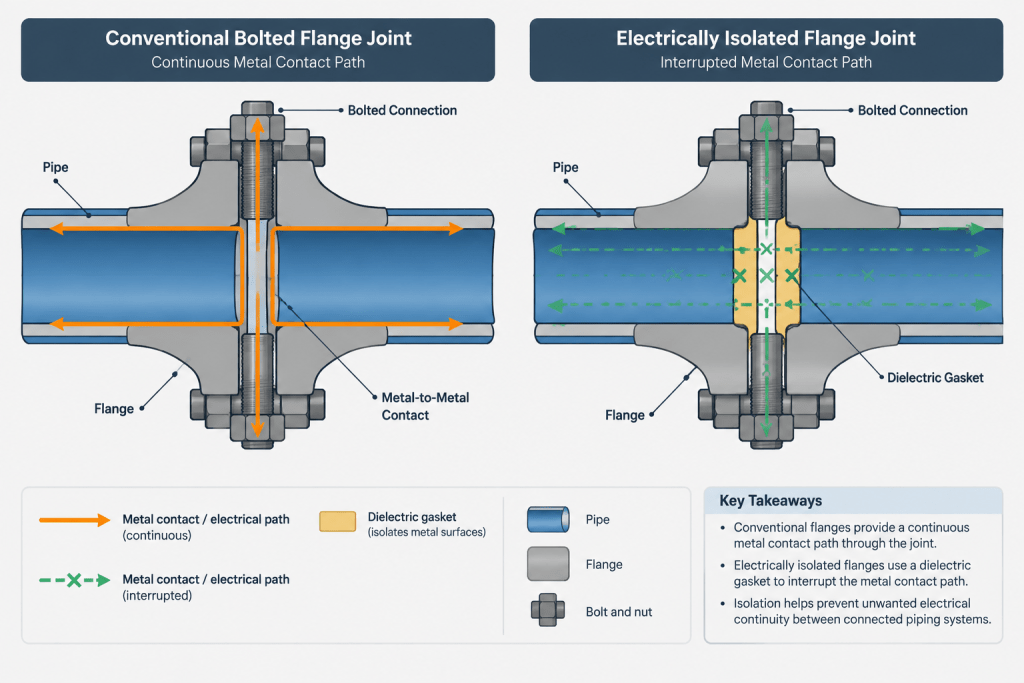
A conventional flanged connection creates multiple possible metal-to-metal paths. The flange faces may be separated by a gasket, but studs or bolts can still electrically bridge the two flanges through their contact with bolt holes, nuts, and washers. An isolation kit is arranged to interrupt these paths.
The gasket separates the flange faces while insulating sleeves and washers separate the fasteners from one or both sides of the joint. Steel washers are often used outside insulating washers to distribute the nut load and protect the insulating material. Kit designs vary, so this general arrangement must not replace the approved product details.
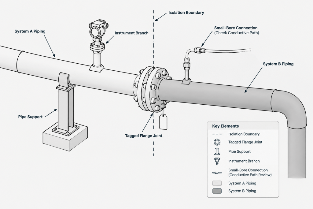
Electrical isolation is not established by appearance alone. Coatings, conductive debris, damaged sleeves, moisture, incorrect washer placement, and connected supports or small-bore lines can create unintended parallel paths. CAD documents the intended assembly and boundary, while installation quality and field testing confirm whether that intent has been achieved.
Typical Parts of the Assembly
| Part | Primary purpose | CAD and documentation concern |
|---|---|---|
| Insulating gasket | Separates the opposing flange faces and contains the process fluid | Confirm gasket style, bore, flange-facing compatibility, material, and required thickness from verified project data |
| Fastener sleeve | Prevents the stud or bolt from contacting the flange bolt-hole surface | Account for sleeve outside diameter, inside diameter, length, and any effect on fastener selection |
| Insulating washer | Separates the nut or steel washer from the flange | Show the correct side arrangement and include every required washer in the material count |
| Steel backing washer | Distributes load and protects the insulating washer | Include its thickness in the complete bolted-joint stack-up |
| Studs, bolts, and nuts | Clamp the joint | Verify diameter, quantity, material, usable thread, and length for the actual assembly |
Some kits insulate fasteners on both sides of the joint, while others use a different arrangement. Some gaskets include integral sealing and insulating features. Never infer kit contents from a simplified symbol or from a previous project.
Why Joint Stack-Up Changes
An isolation kit can make the required fastener stack different from that of a standard flange joint. The assembly may add insulating and steel washers under each nut, and the selected gasket may have a different installed geometry from the gasket assumed in a preliminary model. These parts affect the grip length and available thread engagement.
A reliable stack-up review follows the fastener axis from one end to the other. Depending on the selected connection, the sequence may include a nut, steel washer, insulating washer, first flange, gasket, second flange, another insulating washer, another steel washer, and another nut. The sleeve generally passes through the relevant bolt holes and must be coordinated with the washer arrangement.
Do not increase bolt or stud length by a guessed allowance. Determine it from the verified flange thicknesses, gasket or kit geometry, washer quantities and thicknesses, nut requirements, and project bolting rules. Also check that a sleeve cannot interfere with nut tightening or extend into a location where it prevents proper seating.
How Much Detail Should the CAD Model Show?
General arrangement and routing models
At a broad layout level, the isolation joint may be represented by ordinary flange geometry plus a dedicated property, tag, or note. The key requirement is that the isolation boundary remains visible to reviewers and survives data extraction. Modeling every washer is usually unnecessary when the drawing scale cannot communicate that detail.
Piping isometrics
An isometric should identify the joint as isolated rather than showing it as a standard gasketed connection. The callout should connect to the piping material specification, line-class requirement, isolation-joint schedule, or approved kit description used by the project. If the fasteners differ from normal line-class bolting, that difference must appear in the material data.
Fabrication and installation details
A detail drawing can show the gasket, sleeve, insulating washers, steel washers, nuts, and flange faces in an exploded or sectional view. This is useful when washer placement is not obvious or when multiple isolation-kit configurations exist on the same project. Clearly mark the view as schematic unless every displayed dimension has been verified for the selected product and flange combination.
CAD Properties Worth Tracking
A generic component name such as “gasket” is not enough to protect the design intent. Useful attributes for an isolation-joint record may include:
- Isolation-joint identifier or tag
- Associated line numbers or systems on each side
- Nominal pipe size and flange description
- Flange facing and joint type
- Kit or gasket description from the approved specification
- Fastener sleeve requirement
- Insulating and steel washer arrangement
- Bolting description and verified length source
- Responsible engineering discipline
- Status of vendor-data and field-test requirements
These properties make it easier to locate isolation boundaries, review bills of material, and distinguish intentional isolation from an ordinary flanged break. The fields should match the project’s data structure rather than creating a second naming system used only in CAD.
Common Drafting and Modeling Errors
- Calling out only an insulating gasket: This can omit the sleeves and washers needed to isolate the fasteners.
- Using standard flange bolting automatically: Added washers and kit geometry may change the required stud or bolt length.
- Counting washers per joint instead of per fastener: Material quantities can be understated substantially if the assembly basis is misunderstood.
- Showing insulation on the wrong side: The washer arrangement must follow the selected kit and installation detail.
- Ignoring bolt-hole clearance: A sleeve occupies space inside the flange hole and must be compatible with the selected fastener and flange.
- Losing the isolation boundary during model conversion: A graphical symbol without a persistent property may disappear from exported data or simplified views.
- Assuming the flange kit isolates the whole system: Supports, bonding conductors, instrument tubing, drains, vents, or other metallic connections may bypass the intended boundary.
A Practical CAD Review Workflow
- Locate the required boundary. Confirm why isolation is shown and identify the connected systems on both sides.
- Verify the flange pair. Check size, facing, alignment, bolt-hole pattern, and compatibility with the specified gasket or kit.
- Confirm kit contents. Determine whether sleeves and insulating washers are required on one or both ends and whether steel backing washers are included.
- Build the joint stack. List every part along the fastener axis instead of relying on a standard bolting template.
- Resolve fastener data. Obtain the required length and material from controlled project calculations, specifications, or approved supplier information.
- Check the bore and gasket position. Confirm that the gasket does not create an unintended restriction or interfere with flange sealing geometry.
- Update the BOM. Count gaskets, sleeves, insulating washers, steel washers, studs or bolts, and nuts using the correct unit basis.
- Coordinate adjacent items. Review supports, grounding or bonding provisions, instruments, tracing, and small-bore connections for unintended conductive paths.
- Add installation and test references. Point to the controlled project procedure rather than placing unverified acceptance criteria on the drawing.
Isolation Kits Versus Other Insulating Connections
A flange isolation kit is not interchangeable with every device described as a dielectric or insulating connection. Insulating unions, monolithic isolation joints, lined components, and specially engineered flange assemblies have different construction, installation, inspection, and maintenance implications. The piping model should use the correct component category and should not represent one device with another merely because both interrupt electrical continuity.
For layout purposes, also consider access. A bolted kit can require inspection, retightening under an approved procedure, testing, or replacement. Nearby structural steel, clamps, and piping should not block fastener removal or encourage accidental bridging across the connection.
Final Review Principle
The central CAD task is to preserve the isolation intent while accurately representing the mechanical joint. Identify the boundary, show or reference the complete kit arrangement, calculate the bolting stack from verified data, and keep every component visible in the material record. Final suitability still depends on engineering review, the piping specification, selected supplier data, installation procedures, and field verification.
Managing the Isolation Joint Through Design Changes
An isolation joint should remain traceable when the line class, flange selection, gasket description, or bolting arrangement changes. A revision to either adjoining system can affect the joint even when its location remains unchanged. Review workflows should therefore treat the isolation record as a coordinated assembly rather than an isolated annotation.
When a model is revised, compare the graphical connection, component properties, isometric callout, and bill of material. These outputs should describe the same intended arrangement. If supplier information is still pending, identify that status clearly instead of filling incomplete fields with assumed values.
Information ownership and handoff
The piping team may control the modeled flange assembly, while another discipline defines the electrical-isolation boundary or testing requirement. Project procedures should identify who approves the kit description, who resolves bolting changes, and who confirms that nearby conductive connections do not defeat the intended boundary.
Procurement descriptions also need enough distinction to prevent an isolation kit from being replaced by a conventional gasket and ordinary washer set. At handoff, reviewers should be able to connect the model record to the controlled specification, supplier submittal, installation detail, and applicable inspection procedure without relying on informal notes.
Model QA Questions for Final Coordination
- Is the isolation boundary identifiable in the model and every required drawing output?
- Does the component record distinguish the complete kit from a conventional gasket?
- Are sleeves and both washer types included according to the approved arrangement?
- Was fastener selection reviewed against the complete joint stack rather than a default flange template?
- Do material quantities use the correct basis for each fastener location?
- Are pending supplier details and engineering decisions visibly controlled?
- Have supports, instruments, tubing, bonding provisions, and other possible parallel paths been coordinated?
- Can installation and inspection personnel locate the governing detail or procedure?
A successful CAD deliverable does more than depict two flanges. It maintains a reliable connection between engineering intent, assembly geometry, purchasing data, installation instructions, and verification records.
Frequently Asked Questions
Is an insulating gasket alone a complete flange isolation kit?
Not necessarily. The gasket can separate the flange faces, but fasteners may still provide a conductive path. The specified assembly may also require sleeves, insulating washers, steel backing washers, and coordinated bolting. Use the approved kit and project requirements.
Should every sleeve and washer be modeled in a piping model?
The appropriate detail depends on the model purpose. General arrangement models can use a persistent component property or dedicated identifier, while fabrication and installation details may need a sectional or exploded representation. Material records must still account for all required parts.
Why can an isolation kit affect stud or bolt length?
Added insulating and steel washers, sleeve coordination, and the selected gasket arrangement can change the complete fastener stack. Length should be established from verified assembly data and project bolting rules rather than a guessed addition to standard bolting.
How should an isolation kit appear on an isometric?
The isometric should clearly distinguish the connection from an ordinary gasketed flange joint and reference the controlled project description. Any nonstandard bolting or kit components should also be represented correctly in the material data.
Can CAD confirm that the installed joint is electrically isolated?
No. CAD communicates the intended boundary and assembly. Installation condition, contamination, damaged components, moisture, and conductive bypasses can affect actual performance, which must be addressed through the applicable field inspection and testing process.
What should be checked when the adjoining piping changes?
Recheck flange compatibility, gasket or kit selection, the complete bolting stack, component properties, material quantities, drawing callouts, and nearby conductive connections. A change on either side can affect the coordinated isolation assembly.