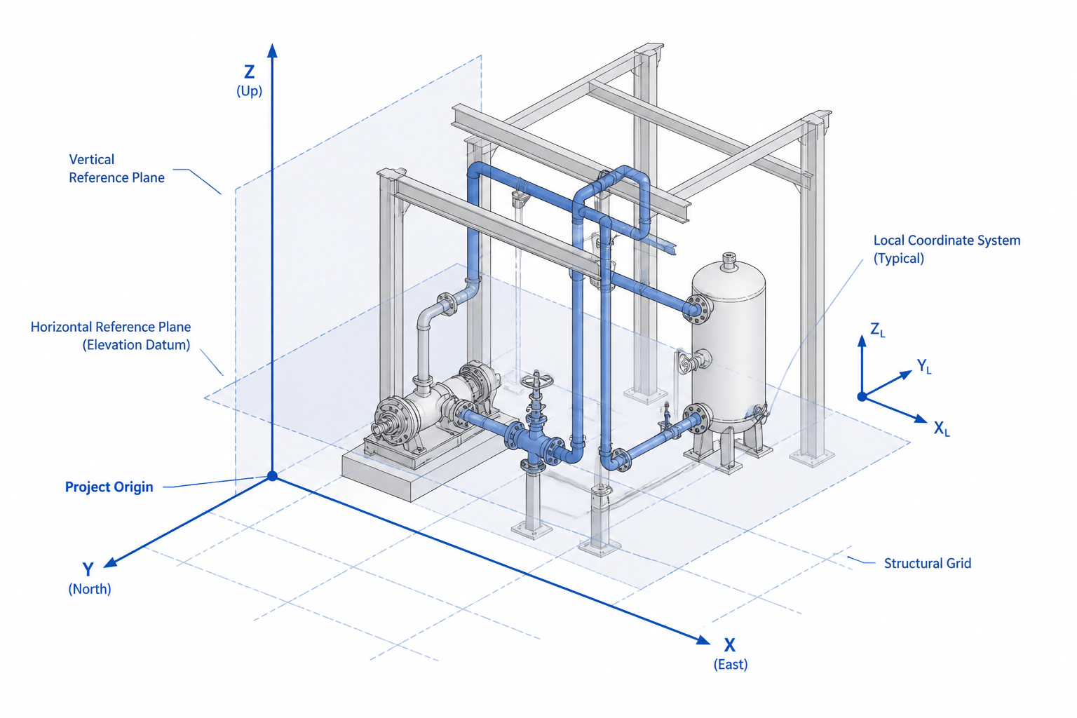
In a piping CAD model, location control is as important as geometry. A pipe may have the correct size, fittings, and route yet still create coordination problems if its position is based on an unclear origin or inconsistent axis system.
Datums and coordinate systems provide the common language for placing piping in relation to equipment, structural grids, buildings, pipe racks, survey information, and linked discipline models. This guide explains how to establish those references, document local systems, and check model placement throughout the design process.
Accurate piping CAD work depends on more than correctly modeled pipe and fittings. Every component must also occupy the intended position relative to equipment, structures, buildings, steel, and other systems. That relationship is controlled through datums and coordinate systems.
When coordinate control is weak, a model can look correct in isolation while being displaced from the project layout. Common symptoms include equipment nozzles that do not meet pipe ends, pipe racks that appear shifted, inconsistent elevations between drawings, and dimensions that cannot be verified against survey or civil information.
This guide explains how to use project datums, local origins, user coordinate systems, and reference geometry in a practical piping CAD workflow. It focuses on model organization and checking rather than project-specific code requirements.
What a datum means in piping CAD
A datum is a defined reference used to locate or compare geometry. It may be a point, line, plane, axis, elevation, grid intersection, building face, or established coordinate value. The datum itself is not usually a physical piping component. It is a control reference that gives dimensions and positions a consistent meaning.
Typical piping datums include:
- Plant or site coordinate origin
- Building grid lines and column lines
- Finished floor or structural reference elevations
- Equipment centerlines and nozzle centerlines
- Pipe rack column lines and deck elevations
- Survey control points or battery-limit references
- Model grid planes used for routing and review
A useful datum should be stable, clearly named, and understandable to everyone who uses the model. A temporary drafting point or an arbitrary object corner is usually a poor long-term reference because it may change during revisions.

Project coordinates and local coordinates
Most piping projects use a project-wide coordinate system to coordinate plant areas, equipment, structures, and discipline models. The coordinates may be expressed as northing, easting, and elevation, or with another project-defined convention. The important point is not the label format but the agreed meaning of each axis and direction.
Designers often also use a local coordinate system for a skid, equipment package, building area, or spool. A local system can make modeling easier because dimensions are shorter and the working view is easier to understand. However, it must remain tied to the project system through a documented origin and orientation.
| Coordinate approach | Useful for | Main control concern |
|---|---|---|
| Project coordinate system | Overall plant coordination and model federation | Axis directions, units, and origin must be consistent |
| Area coordinate system | Building, unit, or pipe-rack modeling | Its relationship to the project system must be recorded |
| Equipment or package system | Vendor models and compact package layouts | Rotation, elevation, and connection points must be verified |
| Temporary user coordinate system | Detailing, editing, and view control | It should not silently redefine project coordinates |
Set the coordinate rules before modeling
Before creating a piping model, identify the project rules that affect location. At minimum, confirm the drawing or modeling units, axis directions, elevation reference, coordinate origin, and whether the model uses true project coordinates or a controlled local origin.
Also determine how linked files are positioned. Architectural, structural, equipment, electrical, and civil models may use different origins or export conventions. A file that looks aligned after a manual move may still have incorrect coordinates if the transformation is not recorded.
Create a short coordinate-control note for the work area. It can identify:
- Project origin and axis orientation
- Reference elevation and its description
- Local origin, if one is used
- Rotation between local and project axes
- Reference grids, equipment centerlines, or survey points
- Rules for exporting, linking, and exchanging CAD files
This information belongs in the model setup, title-block notes, or project control documentation according to the project’s established process. It should not exist only in the memory of one designer.
Use equipment and grids as meaningful references
Equipment is often a better routing reference than an arbitrary model origin because nozzles, centerlines, and access features directly influence piping geometry. When modeling a connection, reference the nozzle location and orientation rather than estimating its position from a visual image.
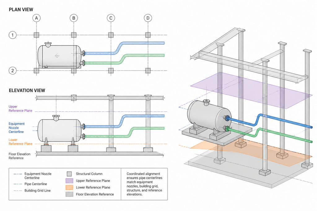
Structural grids provide a second important layer of control. Pipe centers, support locations, rack edges, and access routes can be checked against columns, beams, and deck elevations. A pipe that is dimensionally correct from an origin may still conflict with structure if the structure was positioned from a different reference.
Use reference geometry to make these relationships visible. Construction lines, planes, grid labels, and point markers can help reviewers understand why a pipe is located where it is. Keep reference geometry distinguishable from deliverable piping so it is not mistaken for physical material.
Local origins and model transformations
Large project coordinates can be inconvenient in some CAD environments. A local origin may improve editing performance, reduce coordinate-entry errors, and make dimensions easier to interpret. The local origin is acceptable only when its relationship to the project coordinate system is controlled.
Document the transformation using plain language and project-approved notation. State where the local origin is located, how the local axes point, and how elevation is treated. If the local model is rotated, identify the rotation rather than relying on a saved view or an informal instruction such as “turn it until it matches.”
When importing or exporting a model, verify the transformation with more than one known point. A single point can confirm translation but not rotation. Two or more separated points, or a point plus a known axis, provide a stronger check of position and orientation.
Coordinate checks for piping models
Coordinate checking should be performed during modeling, not only after a complete area is finished. The following workflow is practical for most piping CAD environments:
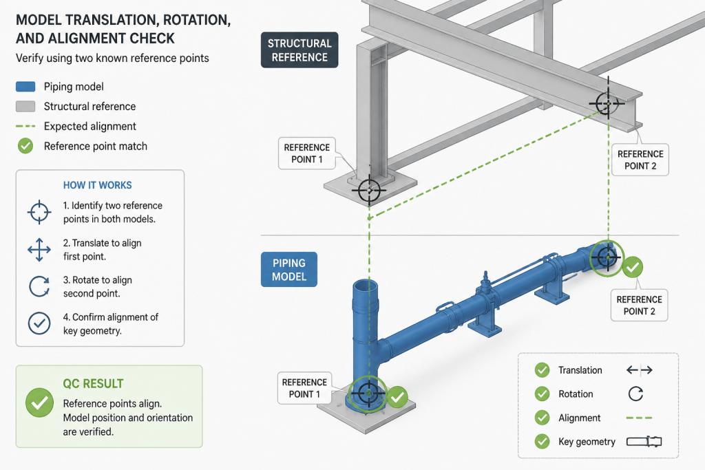
- Confirm the reference file. Load the approved structural, equipment, or survey reference and verify that it is the intended revision.
- Check a known point. Compare a nozzle, grid intersection, floor reference, or other controlled point against the project information.
- Check orientation. Confirm that north, east, elevation, and model axes have the intended directions.
- Check a second point. Use a separated location to detect rotation, mirroring, or scale problems.
- Check elevations. Compare pipe centerlines and equipment connections with the applicable floor, deck, or nozzle references.
- Check linked models. Confirm that structure and equipment remain aligned after reload, export, or file exchange.
- Record exceptions. Mark unresolved coordinate questions instead of hiding them with local edits.
Pay particular attention to mirrored models, rotated equipment packages, and drawings created from extracted views. These can appear visually plausible while reversing an axis or changing the interpretation of coordinates.
Coordinate dimensions on drawings
A drawing should make clear what a coordinate or elevation is measured from. Avoid placing an isolated value near a pipe and assuming the reader knows the reference. Dimension strings, grid labels, datum symbols, and notes should identify the controlling reference.
Use the view that best communicates the relationship. Plans are generally useful for horizontal location, elevations for vertical position, and sections for relationships hidden in plan. Where a single view cannot show the full control scheme, combine a coordinate callout with a clear datum label.
Do not mix local and project coordinates without labeling the difference. A local dimension may be useful for fabrication or area layout, while a project coordinate may be needed for interdisciplinary coordination. Both can appear in the same deliverable, but their purposes and references must be unambiguous.
Common coordinate-control failures
- Unrecorded manual moves: A reference model is shifted until it looks aligned, but the offset is not documented.
- Wrong axis convention: A file uses a different positive direction or swaps horizontal axes.
- Elevation confusion: A floor elevation, structural top, pipe centerline, and equipment datum are treated as the same reference.
- Package rotation errors: A vendor model is inserted with the correct origin but incorrect orientation.
- Stale reference files: Piping is checked against an older structural or equipment arrangement.
- Hidden local systems: A designer uses a temporary coordinate system that remains active during later dimensioning or export.
- Scale or unit mismatch: Imported geometry has the wrong size even though its origin appears correct.
Practical review checklist
Before issuing a model or drawing, ask:
- Can another designer identify the project origin and axis directions?
- Is the elevation reference explicitly defined?
- Are local origins and rotations documented?
- Do equipment nozzles, structural grids, and pipe centerlines agree?
- Have at least two known locations been used to check model placement?
- Are drawing coordinates labeled with their reference datums?
- Will the model remain aligned after export, reload, or coordination exchange?
Good coordinate control turns CAD geometry into dependable project information. It allows piping relationships to be checked against equipment, structures, and other disciplines without relying on visual judgment alone. Use project datums for shared control, local systems only when they are documented, and repeatable checks whenever models are exchanged or revised.
Why coordinate control matters in piping design
Coordinate errors often remain hidden when a model is reviewed by itself. The problem becomes visible when piping is compared with equipment nozzles, structural members, civil information, or another designer’s drawing. A controlled coordinate workflow reduces dependence on visual alignment and makes model decisions easier to review and reproduce.
The most reliable approach is to separate shared project references from temporary drafting aids. Project datums should remain stable across disciplines and revisions. Local origins and user coordinate systems can simplify detailed work, but only when their location, orientation, and relationship to the project system are recorded.
How to read the existing guide
The guide below moves from basic terminology to practical model control. It covers the difference between project and local coordinates, the information to establish before modeling, the use of equipment and structural grids as references, and checks for imports, exports, drawings, and linked models.
Use the coordinate-control ideas alongside the project’s approved CAD procedures and reference information. The purpose is to improve clarity and coordination; project-specific requirements still govern the final model and deliverables.
Frequently Asked Questions
What is a datum in piping CAD?
A datum is a stable reference used to locate or compare geometry. It may be a point, line, plane, axis, elevation, grid intersection, building face, or established coordinate reference.
What is the difference between project and local coordinates?
A project coordinate system supports coordination across the plant or site. A local coordinate system supports work within an equipment package, skid, building area, or other controlled region. The local system must remain tied to the project system through a documented origin and orientation.
Why should equipment nozzles be used as routing references?
Nozzles and equipment centerlines directly control many piping connections. Referencing their controlled location and orientation is more reliable than estimating a connection from a visual image.
How can a local origin be controlled?
Document where the local origin is located, how its axes are oriented, how elevation is treated, and any rotation relative to project coordinates. Verify the transformation using separated known points or a known point and axis.
What should be checked after importing or exporting a CAD model?
Check a controlled point, axis direction, elevation, a second separated location, and the alignment of linked equipment or structural models. These checks can reveal translation, rotation, mirroring, scale, or unit problems.
How should local and project dimensions appear on drawings?
Label each dimension with its controlling datum or reference system. Local dimensions and project coordinates may serve different purposes, but they should not appear together without clear identification.