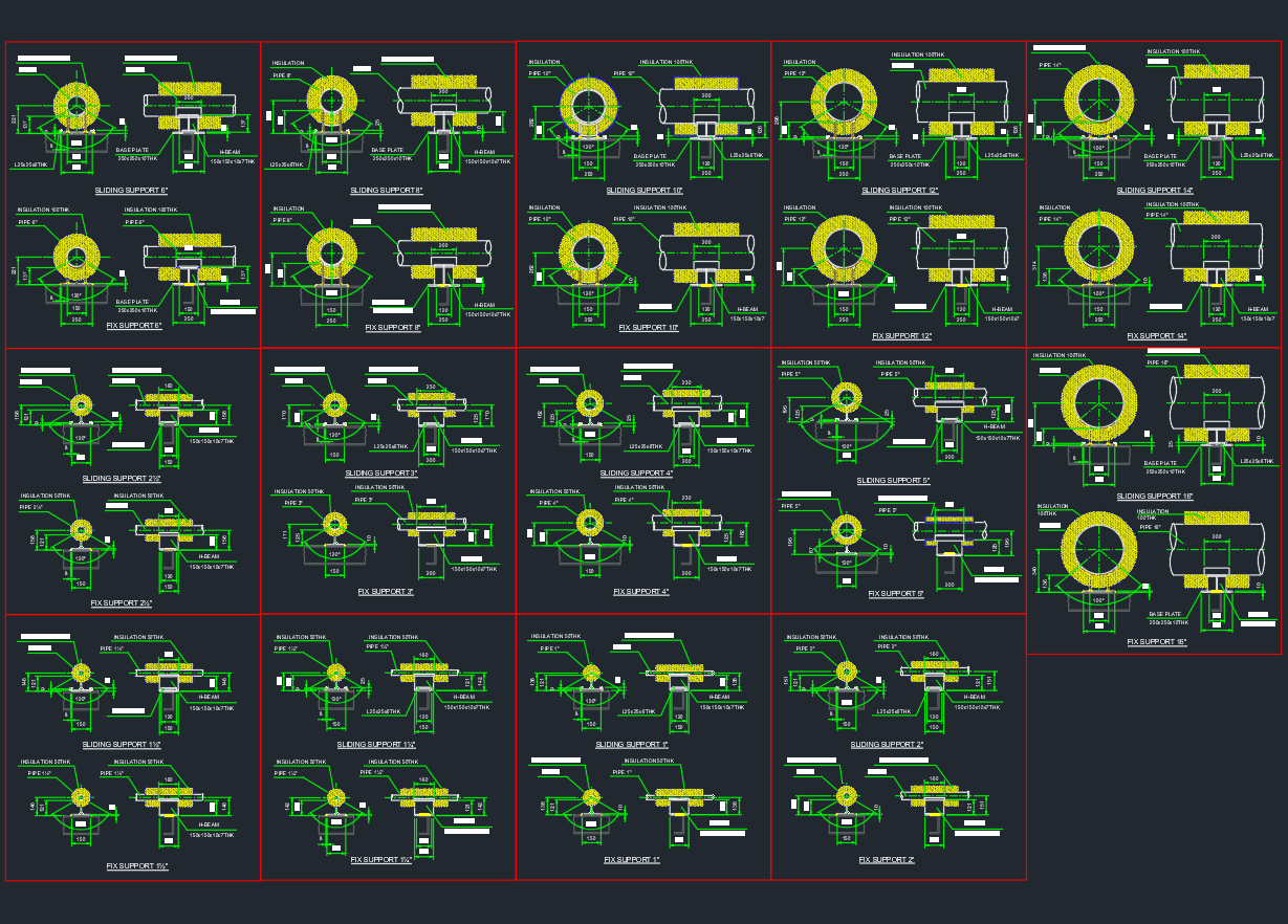
This pipe shoe support details drawing is a practical reference for reviewing how insulated piping can be carried, guided, or restrained above structural steel. Use the sheet alongside project support schedules, piping layouts, insulation requirements, and structural connection information rather than as a standalone design approval.
The drawing is particularly useful when comparing sliding and fixed shoe arrangements, checking how the insulation is accommodated, and coordinating support geometry between piping, structural, and CAD teams. Readers working with pipe support details, insulated pipe supports, and piping CAD drawings can use the existing details as a starting point for disciplined project review.
This pipe shoe support details drawing gives users a clear technical reference for how insulated pipes can be supported using pipe shoes in both sliding and fixed support conditions. The sheet combines many support variations in one organized layout, making it useful for piping design, structural coordination, fabrication, and installation work.
For piping engineers, CAD designers, structural teams, and contractors, this type of drawing is valuable because pipe shoe supports are commonly used where insulation must be protected while the pipe is properly carried and restrained. A well-detailed support drawing helps users understand how the shoe, base plate, support steel, and pipe arrangement work together in real project conditions.
What This Pipe Shoe Support Drawing Shows
The drawing appears to include a series of pipe shoe support details for multiple insulated pipe sizes. Each detail is shown with section and side-style views, helping users understand the pipe position, insulation thickness, support shoe arrangement, and structural mounting condition more clearly.
From the visible layout, the sheet includes:
- sliding pipe shoe supports
- fixed pipe shoe supports
- insulated pipe support details
- base plate arrangements
- H-beam support conditions
- multiple support variations for different pipe diameters
Because many support types are shown together in one sheet, the drawing works as a practical support reference library instead of just one isolated detail.
Why This Drawing Is Useful
A pipe shoe support detail drawing is useful because insulated piping systems often need a support that can carry the pipe load without damaging insulation and, in some cases, still allow movement from thermal expansion. Pipe shoes help create that separation between the insulated pipe and the supporting steel.
This type of drawing helps users understand:
- how insulated pipes sit on the support
- where sliding support conditions may be needed
- where fixed support conditions are required
- how the support connects to the structural steel
- how different pipe sizes affect the support layout
It also improves coordination between piping and structural disciplines by showing the support arrangement more clearly than general notes alone.
Practical Value for Engineers and CAD Designers
For piping engineers, this drawing is useful for reviewing standard support solutions across different insulated pipe sizes. It helps confirm whether a sliding shoe support or fixed shoe support is more suitable for a given location in the piping system.
For structural designers, the drawing gives a reference for how the support frame, base plate, and beam connection carry the piping load. For CAD designers, it serves as a strong example of how to prepare pipe shoe support CAD details in a clean and readable format.
Because multiple support types are included on one sheet, the drawing is also practical as a reusable library for shop drawings and future projects.
A Strong Reference for Insulated Piping Support Documentation
Pipe shoe supports are widely used in steam lines, chilled water systems, process piping, and utility networks where insulation and movement control are both important. A drawing like this is especially useful because it brings together several common support details in one place for easier review.
It is helpful for readers looking for pipe shoe support CAD drawings, sliding pipe support details, fixed support details, or insulated pipe support references. By showing multiple arrangements in one organized sheet, the drawing becomes more practical for real project use.
Conclusion
This pipe shoe support details drawing is a useful reference for understanding how insulated pipes can be supported using both sliding and fixed shoe support arrangements. With multiple pipe sizes, base details, and steel beam support layouts shown in one sheet, the drawing helps users review piping support design more clearly and apply the information more effectively during documentation and construction.
How to Review the Support Details
Begin by identifying the support condition required at the piping location. A sliding shoe is generally reviewed where controlled movement along the supporting surface is part of the piping arrangement, while a fixed shoe is reviewed where the support must restrain the pipe at a defined location. The actual selection should follow the project stress analysis, support philosophy, and engineering requirements.
Next, read the section and side-style views together. Check the relationship between the pipe, insulation, shoe, base plate, and supporting steel. This helps prevent a common drafting error: treating the shoe as an isolated steel item without considering insulation clearance, access for fabrication, or the way the support interfaces with the beam.
Coordination points for project use
- Confirm that the pipe size and insulation arrangement match the applicable detail.
- Check that sliding and fixed conditions are clearly identified on the piping support documentation.
- Coordinate the shoe and base plate with the supporting beam or frame shown in the structural model.
- Verify that the support location agrees with the piping layout and the project support schedule.
- Have loads, restraint forces, welds, fasteners, and structural connections verified by the responsible engineering disciplines.
For CAD users, the sheet can also serve as a reference for organizing a reusable pipe shoe support CAD detail library. Keep each adopted detail traceable to the project specification and revise the drawing when insulation, support steel, or movement requirements change.
Related Reference Topics
This drawing can be reviewed together with resources on pipe dimensions and schedules, pipe fittings, flanges, piping terminology, and CAD and DWG reference practices. Linking these topics helps readers move from component identification to support coordination without confusing a reference detail with a final engineered installation.
Frequently Asked Questions
What is a pipe shoe support?
A pipe shoe is a support attachment that helps carry an insulated pipe while providing a defined interface with supporting steel. Its arrangement may be configured for sliding or fixed behavior, depending on the piping support requirements.
What is the difference between a sliding and fixed pipe shoe?
A sliding pipe shoe is arranged to accommodate specified movement at the support interface, while a fixed pipe shoe is intended to restrain movement at its designated location. The required condition should be confirmed from the piping analysis and support documentation.
Why are pipe shoes used with insulated piping?
Pipe shoes separate the supported pipe from the structural steel and help reduce the risk of compressing or damaging the insulation. The complete arrangement still needs to address insulation clearance, support loads, movement, and installation access.
Can this drawing be used directly for fabrication?
It can be used as a reference for developing project drawings, but fabrication should follow approved project documents. Confirm materials, welds, connections, dimensions, loads, and any applicable specifications before releasing a detail for construction.
Who typically uses a pipe shoe support drawing?
Piping engineers, stress engineers, structural designers, CAD detailers, fabricators, and field installation teams may use this type of drawing during design coordination and document review.