This pipeline crossing detail drawing gives users a clear technical view of how a pipeline can be routed across obstacles such as a river, road, or changing ground profile. The drawing combines several section and profile views, helping users understand how the pipe alignment, support system, and civil elements work together in one coordinated layout.
For piping engineers, civil designers, CAD professionals, and site teams, this type of drawing is useful because crossing points are often the most sensitive parts of a pipeline route. A clear detail drawing makes it easier to review support positions, thrust block locations, level changes, and the relationship between the pipeline and the surrounding terrain.
What This Pipeline Crossing Drawing Shows
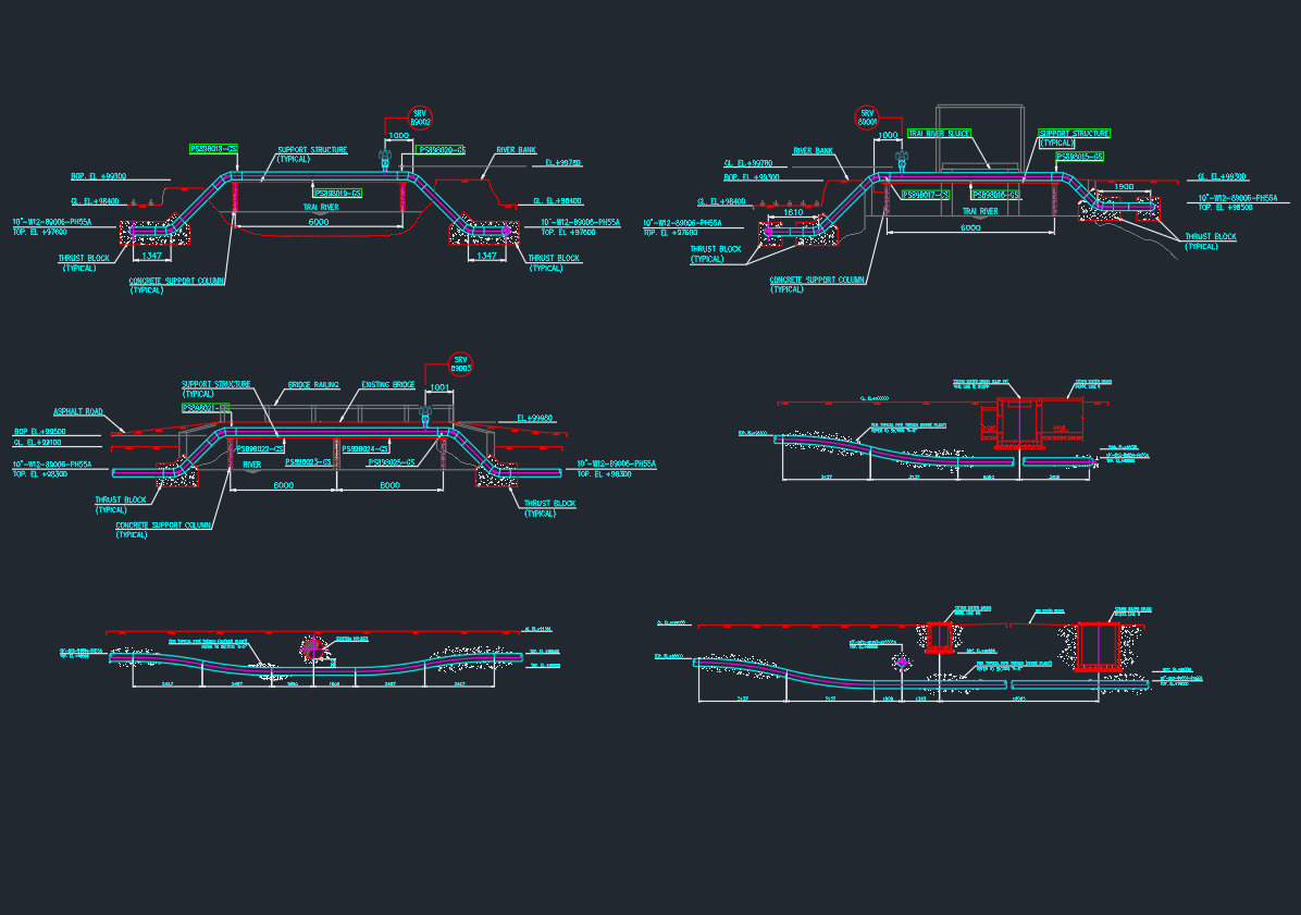
The drawing appears to include several crossing detail views for a pipeline passing over or near a river channel and adjacent ground conditions. It also seems to show a road crossing condition and supporting civil or structural elements used to stabilize the line.
From the visible layout, the drawing includes:
- pipeline profile views
- river crossing arrangement
- road crossing detail
- support structures
- thrust blocks
- concrete support columns
- pipe elevation and top-of-pipe references
Because multiple crossing situations are shown in one sheet, the drawing works as a practical reference for route transitions and special installation zones.
Why This Drawing Is Useful
A pipeline crossing detail drawing is important because changes in terrain, waterways, and road access areas require more than a standard pipe route. These locations often need added support, protection, and civil coordination to ensure the pipeline remains stable and serviceable.
This type of drawing helps users review:
- how the pipeline changes elevation
- where supports are required
- where thrust blocks are placed
- how the pipe interacts with roads or riverbanks
- how the route is controlled through special crossing areas
It also improves communication between piping and civil teams by showing the crossing design more clearly than notes alone.
Practical Value for Engineers and CAD Designers
For piping engineers, this drawing is useful for reviewing how the line is handled at special crossing points. It helps confirm whether the support spacing, profile change, and restraint arrangement are suitable for the crossing condition.
For civil designers, the drawing provides a useful reference for understanding how the pipe interacts with riverbanks, soil profile, road level, and support foundations. For CAD designers, it serves as a strong example of how to prepare a pipeline crossing detail drawing in a clean and readable format.
For site teams and contractors, the drawing also offers practical value during installation because it helps clarify the intended route and support arrangement before construction begins.
A Strong Reference for Pipeline and Civil Coordination
Pipeline crossings are common in utility, industrial, water, and process infrastructure projects. A drawing like this is valuable because it focuses on the exact locations where coordination is most important. Instead of showing only a straight pipeline route, it explains how the pipe behaves at difficult sections of the alignment.
It is especially useful for readers looking for pipeline crossing CAD drawings, river crossing pipeline details, road crossing pipe details, or pipeline support and thrust block references. By combining several profile conditions in one drawing, the sheet becomes more practical for real project use.
Conclusion
This pipeline crossing detail drawing is a useful reference for understanding how a pipeline can be routed across a river, road, and changing ground conditions using supports, thrust blocks, and profile adjustments. With multiple crossing views shown in one organized sheet, the drawing helps users review the design more clearly and apply the information more effectively during coordination and construction.