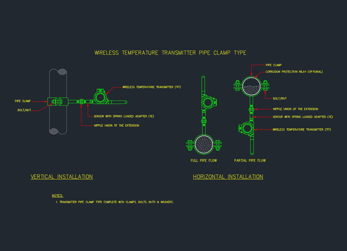
This wireless temperature transmitter pipe clamp detail shows how a clamp-mounted temperature sensor and transmitter can be arranged on existing piping. The drawing covers both vertical and horizontal orientations, including horizontal cases with full-pipe and partial-pipe flow.
Use the detail as a drafting and installation reference alongside your project’s instrument list, P&ID, piping specifications, and applicable pipe dimensions. The downloadable DWG provides the graphical arrangement; project engineering must still confirm the sensor, clamp, hardware, materials, access, and environmental requirements.
This CAD detail helps you place a wireless temperature transmitter (TT) on existing piping using a pipe clamp-type temperature sensor (TE)—useful when you need temperature monitoring without welding, hot work, or thermowell penetration.
What’s included in this drawing
-
Wireless Temperature Transmitter (TT) mounted to the sensor assembly
-
Sensor with spring-loaded adapter (TE) for improved surface contact
-
Pipe clamp + bolt/nut hardware for fastening to the pipe
-
Optional corrosion-protection inlay between clamp and pipe
-
Nipple/union extension (typical field installation arrangement)
-
Installation layouts for:
-
Vertical installation
-
Horizontal installation (with full-pipe flow and partial-pipe flow cases shown)
-
When to use a clamp-on TT detail
-
Retrofit projects where you want fast installation and minimal shutdown time
-
Utility piping where a trend / monitoring temperature point is acceptable
-
Locations where cutting the line or adding a thermowell is not allowed
Drafting tips for your drawings
-
Tag clearly on P&ID / instrument list: TE (sensor element) and TT (transmitter)
-
Add a note for surface preparation (clean metal contact area) if your spec requires it
-
If used outdoors, consider showing insulation/weatherproofing around the clamp area (project-dependent)
How to read the pipe clamp temperature detail
The assembly separates the sensing function from the transmitting function. The TE is the pipe-contacting sensor element, while the TT is the wireless temperature transmitter mounted to the sensor assembly. Keeping these tags consistent helps coordinate the CAD detail with the P&ID and instrument list.
Installation features to check
- Pipe contact: Confirm that the sensor contact area, spring-loaded adapter, and clamp arrangement match the pipe surface and the project installation specification.
- Clamp hardware: Review the clamp, bolt, nut, and any corrosion-protection inlay as an assembly rather than treating the clamp as a generic drafting symbol.
- Extension arrangement: The nipple or union extension shown in the detail may affect access, orientation, and clearance around the transmitter.
- Flow orientation: Select the vertical or horizontal view that represents the actual pipe run. For horizontal piping, identify whether the drawing is being applied to the full-pipe-flow or partial-pipe-flow case.
- Environment: Where the installation is outdoors, coordinate insulation and weatherproofing around the clamp area with the project specification.
Why a clamp-on arrangement may be selected
A clamp-mounted sensor can support retrofit temperature monitoring when the project wants to avoid welding, hot work, line cutting, or thermowell penetration. It is commonly considered where a trend or monitoring point is acceptable, but the instrumentation engineer should verify whether the surface-sensing arrangement meets the required measurement purpose.
Drafting and coordination checklist
- Show the TE and TT tags consistently across the CAD detail, P&ID, instrument list, and installation documents.
- Identify the pipe location and installation orientation clearly enough for field personnel to distinguish vertical from horizontal applications.
- Add the required surface-preparation note when clean metal contact is part of the project specification.
- Check access for tightening, inspection, transmitter installation, and future maintenance.
- Coordinate clamp materials, corrosion protection, insulation, and weatherproofing with the piping and instrumentation specifications.
For related drafting work, compare this detail with your internal references for pipe dimensions, piping terminology, P&ID symbols, and DWG instrumentation details.
FAQ
What does the TE represent in this detail?
TE identifies the temperature sensor element, including the clamp-mounted sensor arrangement that contacts the pipe surface.
What does the TT represent?
TT identifies the wireless temperature transmitter mounted to the sensor assembly. The TE and TT should be coordinated across the P&ID, instrument list, and installation drawing.
Can this detail be used on vertical and horizontal piping?
Yes. The drawing includes vertical and horizontal installation layouts. The horizontal arrangement also distinguishes full-pipe-flow and partial-pipe-flow cases, so the applicable view should match the actual piping condition.
Does a clamp-on sensor replace a thermowell in every application?
No. The detail is intended for applications where surface temperature monitoring is acceptable and a thermowell or line modification is not allowed or not desired. Measurement requirements, process conditions, materials, and project specifications must be reviewed by the responsible engineering team.
What should be shown for an outdoor installation?
Coordinate insulation and weatherproofing around the clamp area when required by the project. Also verify that the transmitter and fastening arrangement remain accessible for installation and maintenance.