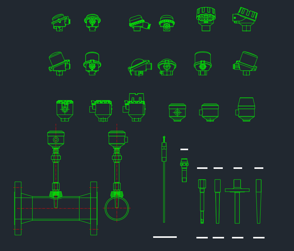
Temperature measurement devices appear in process diagrams, piping layouts, equipment details, and instrumentation documentation. A consistent CAD block helps drafters show the sensing element, transmitter, connection head, thermowell, and mounting arrangement without redrawing common components.
This resource is intended for engineers, designers, and CAD technicians preparing P&IDs, piping drawings, instrumentation layouts, and related documentation. Use the blocks as drafting references, then verify the final symbol, tag, orientation, connection, and installation details against the project legend, instrument index, piping specification, and approved vendor information.
When you’re drafting P&ID, instrumentation layouts, or piping details, using the correct temperature measurement symbols and blocks saves time and keeps your drawings consistent. This CAD set covers common field instruments used for temperature monitoring and control—ideal for mechanical, process, and utility projects.
What you can represent with this set
-
Temperature sensors (typical RTD / thermocouple probe styles)
-
Temperature transmitters and connection head variations (different head shapes and orientations)
-
Thermowell / protection tube style details (probe protection for pressurized lines)
-
Inline / inserted mounting examples on piping (typical installation views)
-
Probe stem / extension options for different insertion lengths and site conditions
How to use it in real drawings
-
On P&ID, tag instruments clearly (examples: TE, TT, TI) to match your instrument index.
-
On piping/isometric, show thermowell + probe when the line is pressurized or high-velocity, and show direct insertion only when allowed by spec.
-
Keep one consistent block style for all sheets so construction and commissioning teams can read it fast.
How to choose the right temperature instrument block
The visible device on a drawing depends on what the drawing needs to communicate. A sensor block may represent the probe or sensing element, while a transmitter block shows the field device that receives the measurement and communicates it to the control or monitoring system. A connection head can indicate the physical termination around the sensor and its wiring connection.
- RTD representation: Use an RTD-style sensor block when the drawing needs to identify a resistance-based temperature sensing element.
- Thermocouple representation: Use a thermocouple-style block when the sensing device is based on a thermoelectric measurement arrangement.
- Transmitter representation: Show the transmitter when the instrument loop, field device, or signal path must be coordinated with the instrument index and control documentation.
- Thermowell representation: Show the thermowell or protection tube when the installation requires a protective interface between the process and the sensing probe.
- Direct-insertion representation: Use an inserted probe view only when the project specification and installation design permit that arrangement.
Drafting workflow for temperature instruments
Start by identifying the measurement point and the document type. A P&ID generally needs clear instrument identification and loop coordination, while a piping or isometric drawing may need the physical mounting arrangement, thermowell, probe extension, and relationship to the pipe.
Coordinate the block with the instrument index, P&ID symbol legend, piping isometric standards, and CAD layer conventions. The block should support the drawing rather than substitute for the approved instrument data. Confirm process connection details, insertion arrangement, accessibility, orientation, and materials from the applicable project documents before issuing construction or fabrication drawings.
Related drafting references
For a complete documentation workflow, connect this resource with internal references for P&ID symbols, instrument tag conventions, thermowell details, piping isometric drafting, flange and fitting references, and DWG block resources. These related topics help users move from a symbolic instrument representation to a coordinated piping and installation drawing.
Frequently asked questions
What is included in a temperature sensor CAD block set?
The set represents common temperature sensors, RTD and thermocouple probe styles, transmitters, connection head variations, thermowells or protection tubes, inline and inserted mounting arrangements, and probe stem or extension options.
Should the sensor block be used on a P&ID or a piping drawing?
It can support both, but the information shown should match the document purpose. Use clear instrument identification on a P&ID and show the physical mounting arrangement on piping or isometric drawings when that detail is required.
Does the CAD block establish the instrument dimensions or process connection?
No. A CAD block is a drafting representation. Confirm dimensions, connections, materials, insertion requirements, and other engineering details using the approved project documents, instrument data, piping specification, and vendor information.
When should a thermowell be shown?
Show a thermowell or protection tube when the design requires the probe to be protected from the process or when the piping detail needs to communicate the installed protection arrangement. Final selection and installation must be verified by the responsible engineering team.
How should temperature instruments be tagged?
Use the project instrument index and approved P&ID legend. Common tag examples such as TE, TT, and TI may appear in project documentation, but the governing project convention should control the final tag and symbol usage.