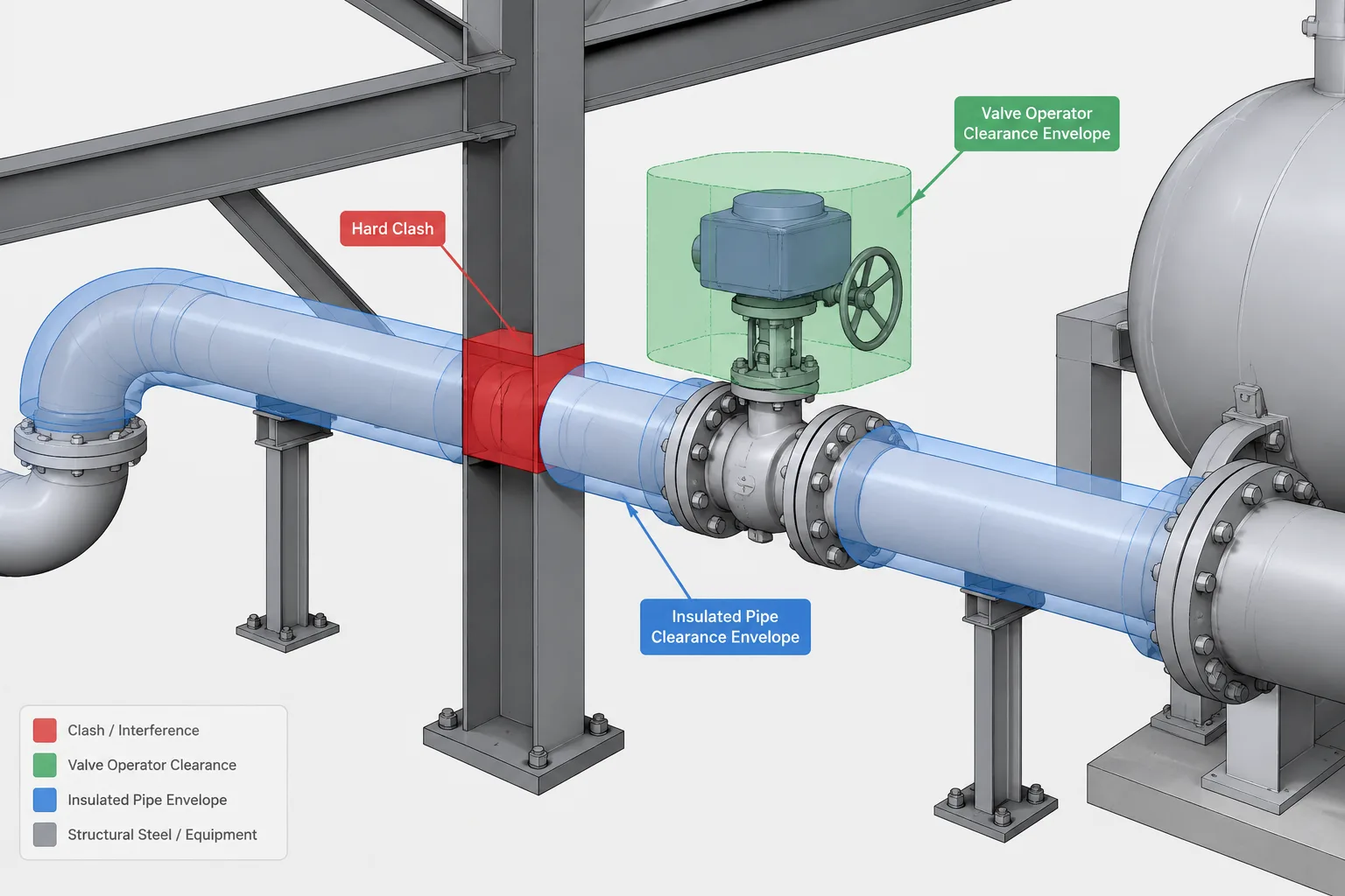
Piping CAD clash detection is most effective when the review is organized around design intent rather than raw interference counts. Physical overlap is only one concern; reviewers must also recognize reserved space, component movement, service access, installation needs, and unreliable model data.
This guide explains how to interpret common clash categories, configure focused reviews, reduce false positives, and document issues so that the responsible discipline can make and verify an appropriate correction.
Piping CAD clash detection is more than finding two solids that occupy the same space. A useful review must also consider insulation, operation, maintenance, thermal movement, installation, and the reliability of the model geometry. A pipe may clear a structure in the model while leaving no practical room for insulation, flange bolting, valve operation, or component removal.
Automated checking can identify geometric conflicts, but it cannot determine every design consequence. The reviewer must understand what each modeled object represents, which clearance rules apply, and whether a reported clash is real, intentional, temporary, or caused by incomplete data.
What Counts as a Piping Clash?
A clash occurs when piping geometry or a required piping envelope conflicts with another object or reserved space. The conflicting object may belong to piping, structural steel, equipment, ductwork, cable tray, electrical systems, architecture, or civil work.
Not all clashes have the same significance. A pipe intersecting a beam is a direct geometric conflict. An operator handle that cannot complete its travel is an operational conflict. A valve that cannot be removed without dismantling unrelated systems is a maintenance conflict. Each requires a different review approach.
| Clash category | Typical condition | Primary concern |
|---|---|---|
| Hard clash | Two physical objects overlap | Fabrication or installation is not geometrically possible |
| Soft clash | Objects do not overlap, but required separation is missing | Insulation, access, safety, operation, or construction |
| Movement clash | An object enters the hot, cold, vibrating, or displaced position of piping | Operation after startup or during transient conditions |
| Maintenance clash | Removal or service space is blocked | Inspection, repair, or replacement |
| Workflow clash | Construction sequence or installation path is obstructed | Assembly, lifting, welding, testing, or temporary works |
| Data clash | Geometry is inconsistent with component data or interface information | False confidence in an inaccurate model |
Hard Clashes: Start with Physical Geometry
A hard clash is usually the simplest type to understand. Examples include a pipe passing through structural steel without a coordinated opening, a flange intersecting a wall, or two piping components occupying the same location.
Even apparently obvious hard clashes require interpretation. A pipe crossing a wall may be correct if a sleeve or penetration is planned but not yet modeled. Overlapping fittings may indicate a routing error, or they may be duplicate objects imported from separate discipline models. A reported interference should therefore be checked against object ownership, model status, and drawing intent before corrective work begins.
Hard-clash reviews should use the actual component envelope rather than only the pipe centerline. Flanges, valve bodies, strainers, branch fittings, supports, actuators, and specialty items often project well beyond the pipe outside diameter. Simplified line representations are useful for early routing, but they cannot provide a complete interference review.
Soft Clashes and Clearance Zones
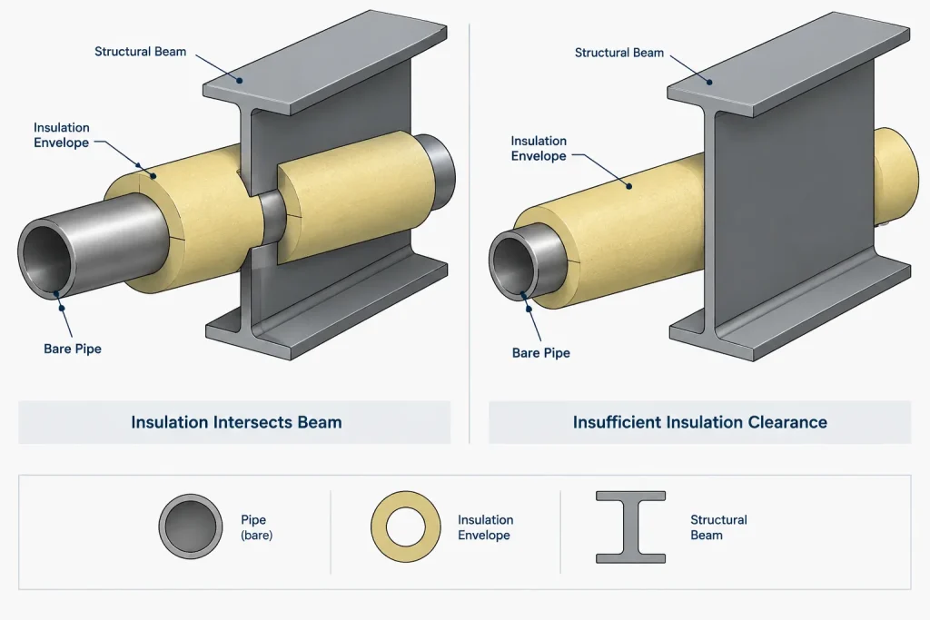
A soft clash occurs when the physical objects remain separate but the available gap is inadequate for the intended use. The model must distinguish between the component itself and any space that must remain clear around it.
Insulation and Protective Systems
Checking bare pipe geometry alone can miss conflicts involving insulation, cladding, heat tracing, fire protection, acoustic treatment, or removable insulation covers. These layers may also change along a line, particularly at valves, flanges, supports, and equipment interfaces.
A practical model may represent these requirements with physical geometry, clearance envelopes, data-driven checks, or a combination of methods. Whatever method is used, reviewers should know whether the visible pipe surface represents metal outside diameter, insulation outside diameter, or a simplified routing envelope.
Operation and Human Access
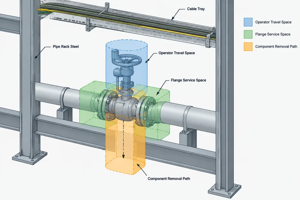
Valve handles, handwheels, levers, chain operators, gearboxes, and actuators require more than a nonintersecting installed position. The operator may need room to rotate, swing, disengage, or be reached safely by personnel.
Access space should not automatically be treated as a permanent solid object. It is often better represented as a review envelope with a clear purpose, such as operator travel, standing access, tool access, or emergency operation. This helps prevent reviewers from treating all clearance volumes as identical.
Bolting and Joint Service
A flange can appear clear while its studs, nuts, tools, or removal direction conflict with nearby steel or piping. Similar concerns apply to grooved couplings, threaded joints, union nuts, clamps, and removable closures. Joint access should be evaluated according to the actual assembly and maintenance method rather than a generic radial offset.
Movement Envelopes Are Not Optional Geometry
A static model usually represents one selected position, but operating piping may move because of thermal expansion, support deflection, equipment nozzle displacement, vibration, settlement, or other imposed movement. A route that is clear in its modeled position may conflict in another credible position.
Movement review should be based on verified engineering input. CAD personnel should not invent displacements or assume that every line expands only along its local axis. Where movement results are available, the model can show displaced positions, swept envelopes, or designated clearance zones. The chosen representation should clearly distinguish calculated movement from drafting allowance.
Flexible connections and expansion joints also need careful interpretation. Their presence does not mean nearby piping can be placed without clearance. Connected equipment, restraints, anchors, guides, and support behavior influence how movement is distributed through the system.
Maintenance and Removal Paths
Many important conflicts do not exist until a component must be serviced. Typical examples include blocked strainer screens, trapped valve internals, inaccessible exchanger channel covers, and pumps whose connected piping prevents equipment removal.
A maintenance review should consider both the extraction envelope and the route by which the item leaves the area. Providing space immediately beside a component is not enough if the item cannot be lifted, lowered, rotated, or transported past adjacent systems.
- Identify components expected to be inspected or replaced.
- Confirm the intended disassembly direction with vendor or project information.
- Include removable covers, internals, fasteners, and handling devices where relevant.
- Check whether unrelated piping must be dismantled to create an exit path.
- Coordinate permanent access platforms, hatches, doors, and lifting provisions.
Generic CAD geometry should not be treated as proof of a manufacturer-specific removal requirement. Vendor information remains necessary when the maintenance envelope depends on internal construction or supplied lifting details.
Why Clash Reports Produce False Positives
A large clash count does not necessarily indicate a poor layout. It may indicate that the test was configured too broadly or that model objects have not been classified correctly.
Common false or low-value results include insulation touching its own pipe, a support intersecting the pipe it supports, bolts overlapping their associated flange holes, intentional penetrations, duplicate reference models, and clearance envelopes intersecting objects they were not intended to test. Construction geometry, hidden placeholders, and obsolete revisions can create additional noise.
The solution is not to ignore the report. The test should be organized into meaningful object groups, with documented exclusions for intentional relationships. Excessive blanket suppression is risky because it can hide later changes at the same location.
A Practical Clash-Review Workflow
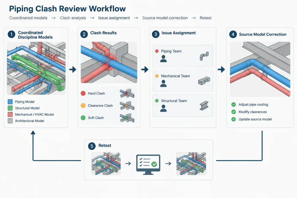
- Confirm model readiness. Verify coordinate alignment, units, revision status, object ownership, and the completeness of major equipment and structure.
- Define the test purpose. Separate physical intersection tests from insulation, access, movement, and maintenance checks.
- Group systems logically. Test piping against relevant disciplines and divide results by area, system, or responsibility where useful.
- Review in context. Inspect nearby components, supports, joints, and access routes rather than viewing only the isolated clash point.
- Classify the result. Mark it as valid, intentional, duplicate, pending information, or not applicable. Record the reason.
- Assign ownership. The discipline moving an object is not always the discipline that discovered the conflict.
- Resolve at the source. Correct the responsible model rather than masking the clash in a coordination file.
- Retest the updated model. A local routing change can create new conflicts elsewhere or invalidate a previous clearance check.
What to Record in a Clash Issue
A useful issue record should let another person find, understand, and verify the problem without repeating the entire investigation. Include the location, affected objects, model revisions, clash category, responsible discipline, current status, and a concise description of the required decision.
Screen captures are helpful, but they should show orientation and surrounding context. An image zoomed tightly onto two intersecting surfaces may not reveal which route can move or whether a nearby nozzle, support, or access zone controls the solution.
Clash-Free Does Not Mean Design-Complete
A coordinated model can pass its configured clash tests and still contain design problems. Automated checks may not recognize poor drainage, inaccessible instruments, unsuitable valve orientation, inadequate support concepts, incorrect component data, or an unverified equipment interface.
Piping CAD clash detection is therefore a design-review tool, not a substitute for engineering judgment, discipline checks, vendor verification, or field coordination. Its greatest value comes from combining reliable geometry, clearly defined clearance envelopes, focused test rules, and accountable issue resolution.
Turning Clash Results into Coordination Decisions
A clash report should be treated as a list of conditions requiring review, not as an automatic list of design errors. Each result must be interpreted against the model purpose, project requirements, component status, and available engineering or vendor information.
Separate Detection from Resolution
Clash software identifies a geometric relationship. It does not necessarily identify the controlling design requirement or the correct object to move. A structural member may appear to obstruct piping, for example, while the practical solution is a piping reroute, a coordinated penetration, an equipment adjustment, or a change to an access strategy. The appropriate decision depends on ownership, constraints, and approved design criteria.
Reviewers should avoid suggesting a routing change before checking nearby nozzles, supports, joints, slopes, movement requirements, and maintenance paths. Moving geometry away from the reported clash point can transfer the problem to another location or create a less visible design issue.
Match the Test to Model Maturity
Early coordination models may contain simplified equipment, approximate structure, and centerline-based routing. These models can support major routing decisions, but they should not be interpreted as proof of detailed clearance. Later reviews can use more complete component bodies, supports, actuators, insulation representations, and verified access envelopes.
The issue status should reflect this maturity. A result caused by missing vendor geometry is better recorded as pending information than accepted as clear. Likewise, placeholder geometry should remain identifiable so it is not mistaken for an approved equipment interface.
Use Acceptance Reasons That Can Be Rechecked
An intentional intersection or approved exception should have a specific reason. Useful explanations identify the coordinated condition, such as a planned penetration, an associated support connection, or an envelope that is not applicable to the tested object group. Vague notes make it difficult to determine whether acceptance remains valid after a revision.
Accepted clashes should be capable of reappearing for review when relevant geometry, model revisions, or design assumptions change. Permanent suppression based only on location can conceal a new and unrelated conflict.
Practical Review Questions
- What does each object represent? Confirm whether the geometry is physical, simplified, temporary, or a reserved envelope.
- Which condition is being tested? Distinguish installed geometry from insulation, operation, movement, removal, and construction access.
- Is the information current? Check model revision, reference alignment, object ownership, and interface status.
- What controls the solution? Consider equipment connections, structure, supports, access routes, movement, and fabrication constraints.
- How will closure be verified? Require an updated source model and a repeatable check rather than relying only on a comment or screen capture.
A disciplined review process turns clash detection from a visual cleanup exercise into traceable multidisciplinary coordination. The objective is not merely a report with fewer entries, but a model in which physical geometry and required working spaces have been evaluated against reliable design information.
Frequently Asked Questions
What is the difference between a hard clash and a soft clash?
A hard clash is a physical overlap between modeled objects. A soft clash occurs when the objects do not overlap but the separation needed for insulation, operation, access, movement, construction, or maintenance is unavailable.
Is pipe centerline geometry enough for clash detection?
Centerlines are useful for routing and early coordination, but they do not represent the full component envelope. A detailed review may also need pipe surfaces, fittings, flanges, valves, actuators, supports, insulation, and purpose-specific clearance zones.
Who should own a piping clash issue?
Issue ownership should follow responsibility for investigating and coordinating the condition. The discipline that reports a clash is not necessarily the discipline that should change its model. The controlling design constraints should be reviewed before assigning corrective work.
Can a clash be closed from a screen capture?
A screen capture can document context, but closure should normally be verified in the updated source model. The affected objects, current revisions, surrounding geometry, and applicable clearance condition should be checked again.
When is an intentional clash acceptable?
An intentional relationship may be acceptable when it represents a coordinated condition, such as a planned penetration or a support connected to the pipe it serves. The reason should be documented clearly and reconsidered when related geometry changes.
Does a clash-free model mean the piping design is complete?
No. A model can pass configured tests while still containing problems involving drainage, support concepts, valve orientation, instrument access, component data, equipment interfaces, or other engineering requirements that the clash rules do not evaluate.