Tag: piping layout
-
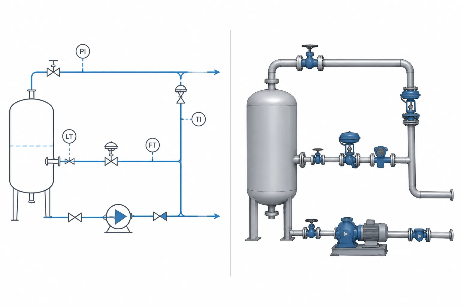
P&ID Symbols vs. 3D Piping Models: Why Functional Diagrams and Physical Geometry Differ
-
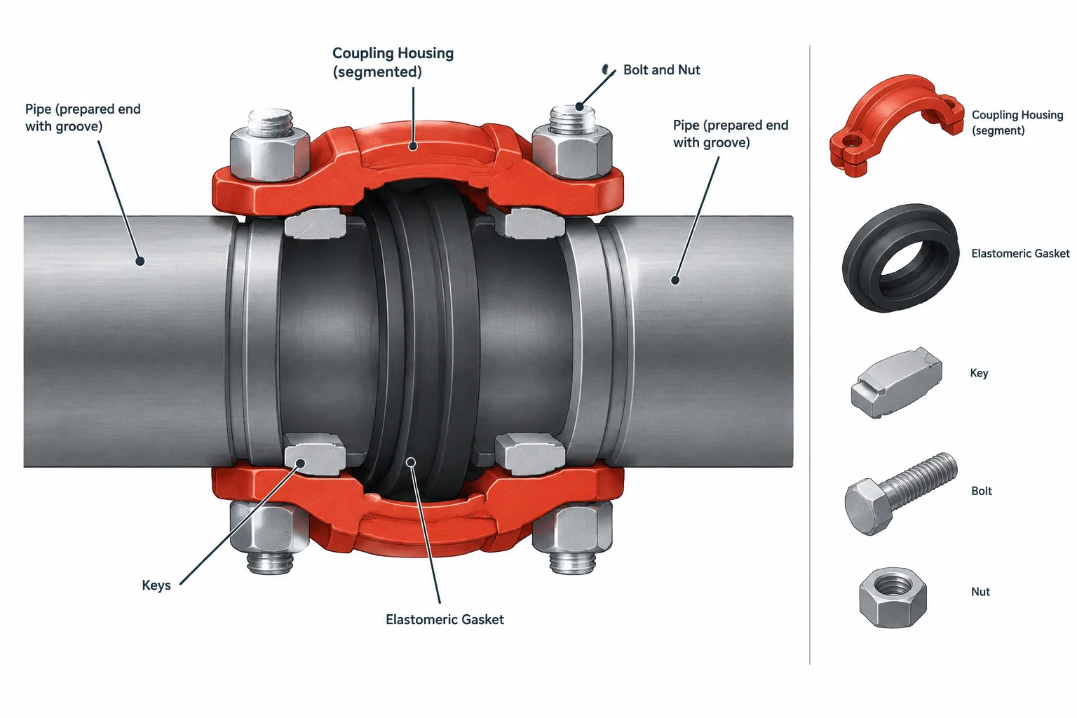
Grooved Pipe Joints in Piping CAD: Couplings, Grooves, Gaskets, and End Gaps
-
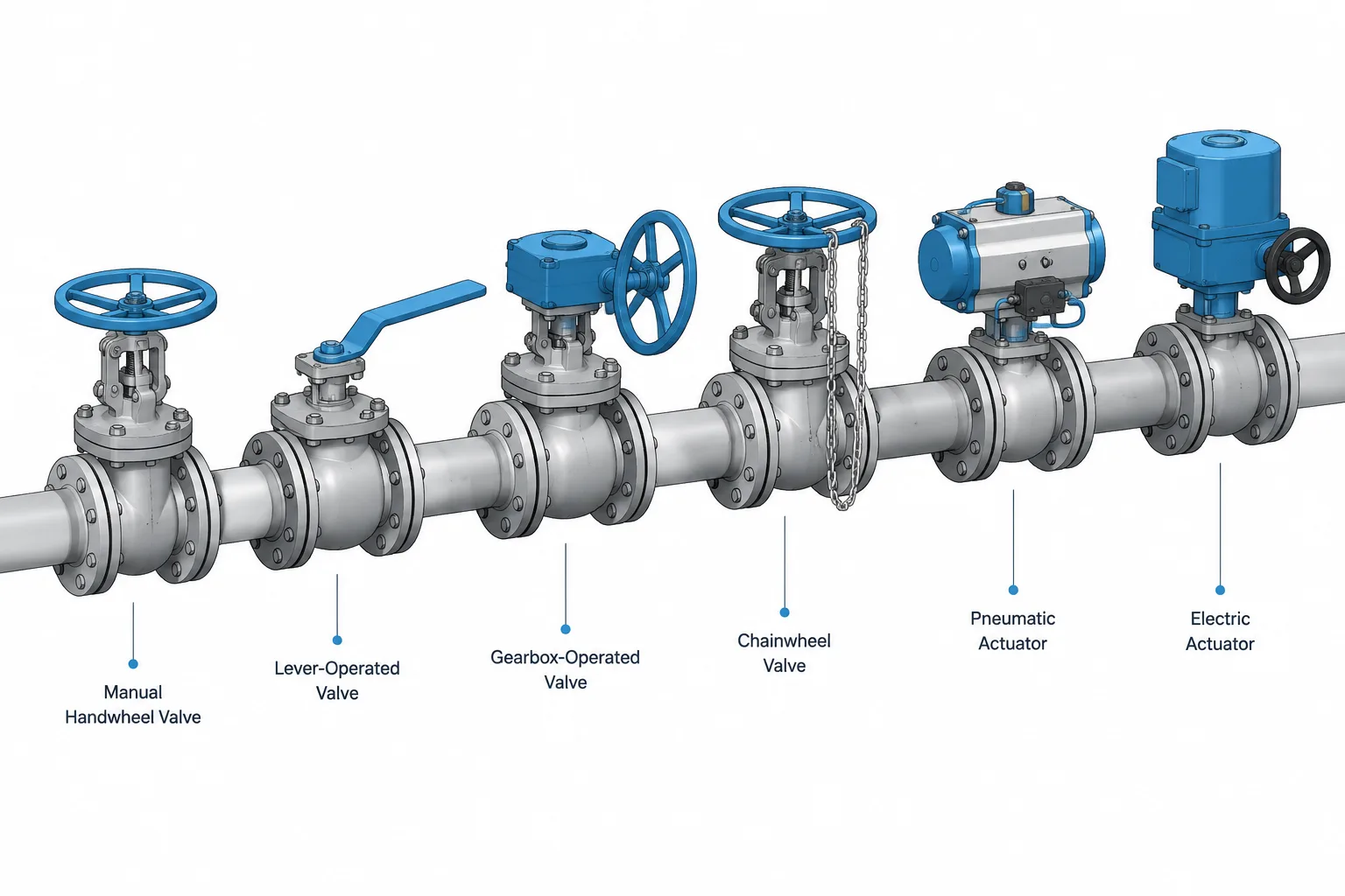
Valve Operator Types in Piping CAD: Handwheels, Gearboxes, Actuators, and Chainwheels
-
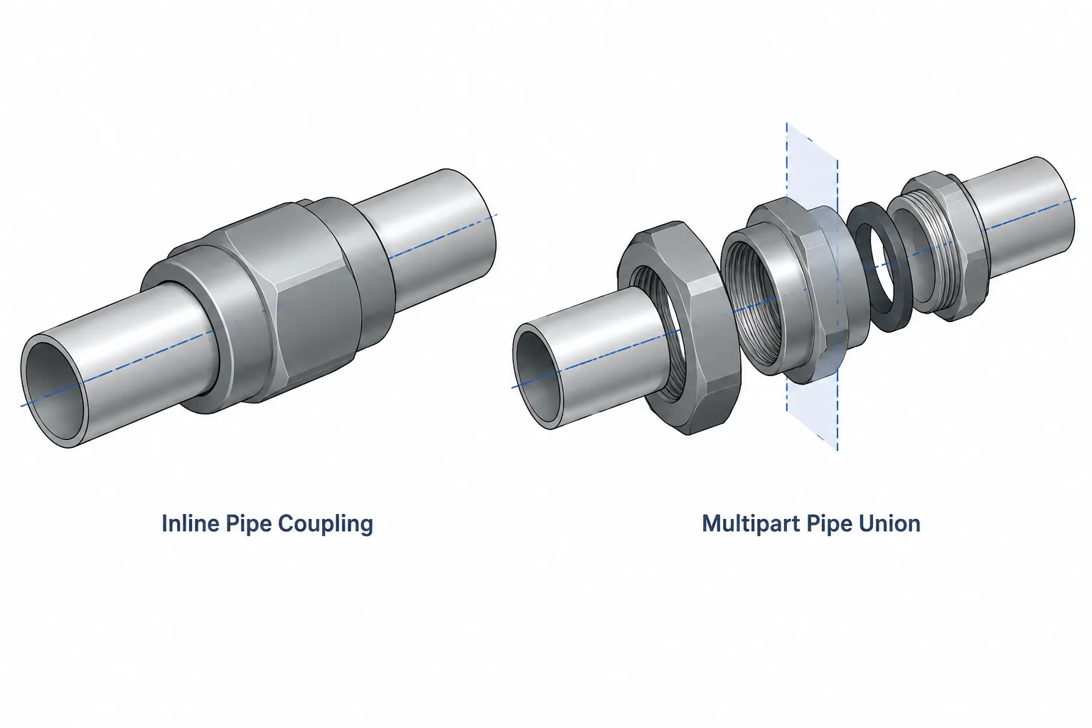
Pipe Unions vs. Couplings in Piping CAD: Connection, Disassembly, and Layout Differences
-
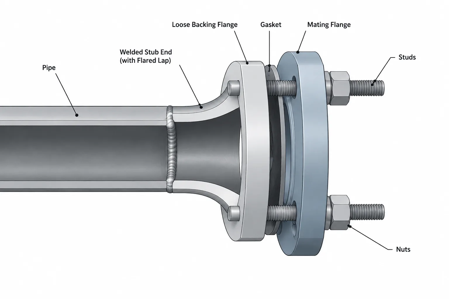
Lap Joint Flanges and Stub Ends in Piping CAD: Assembly, Rotation, and Dimension Control
-
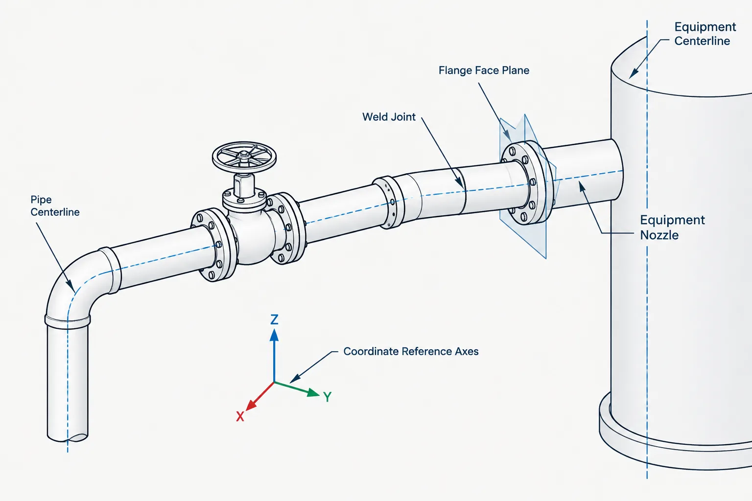
Piping CAD Datums: Centerlines, Face Planes, Weld Lines, and Equipment Interfaces
-
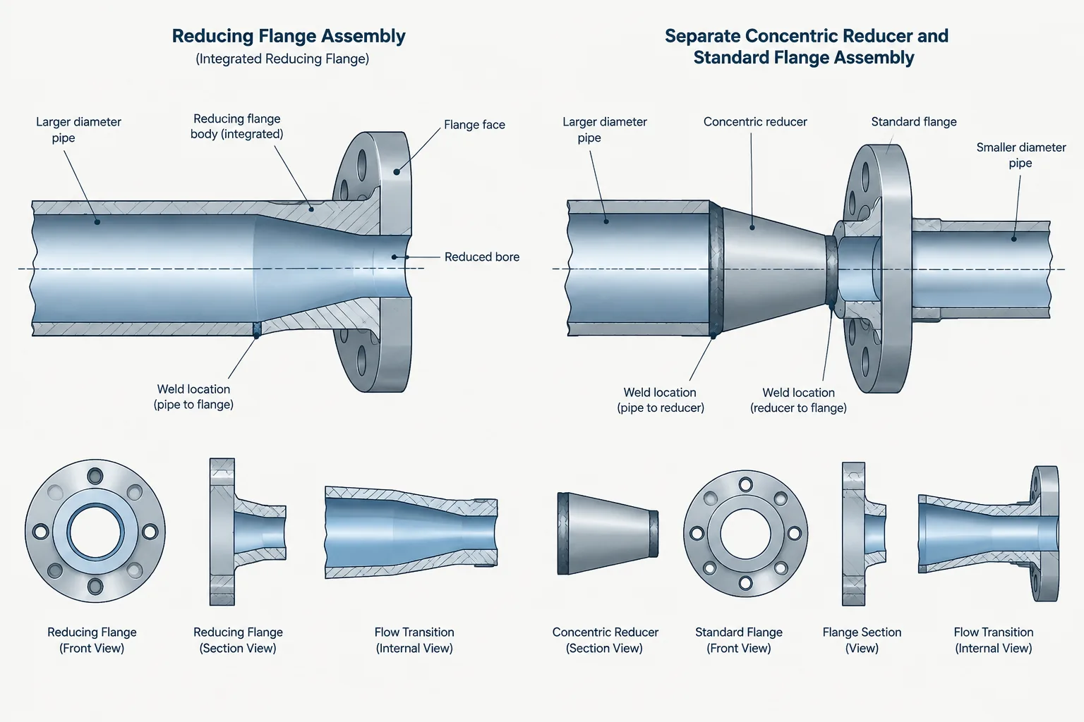
Reducing Flanges vs. Reducers in Piping CAD: Size Transitions, Bolt Patterns, and Layout
-
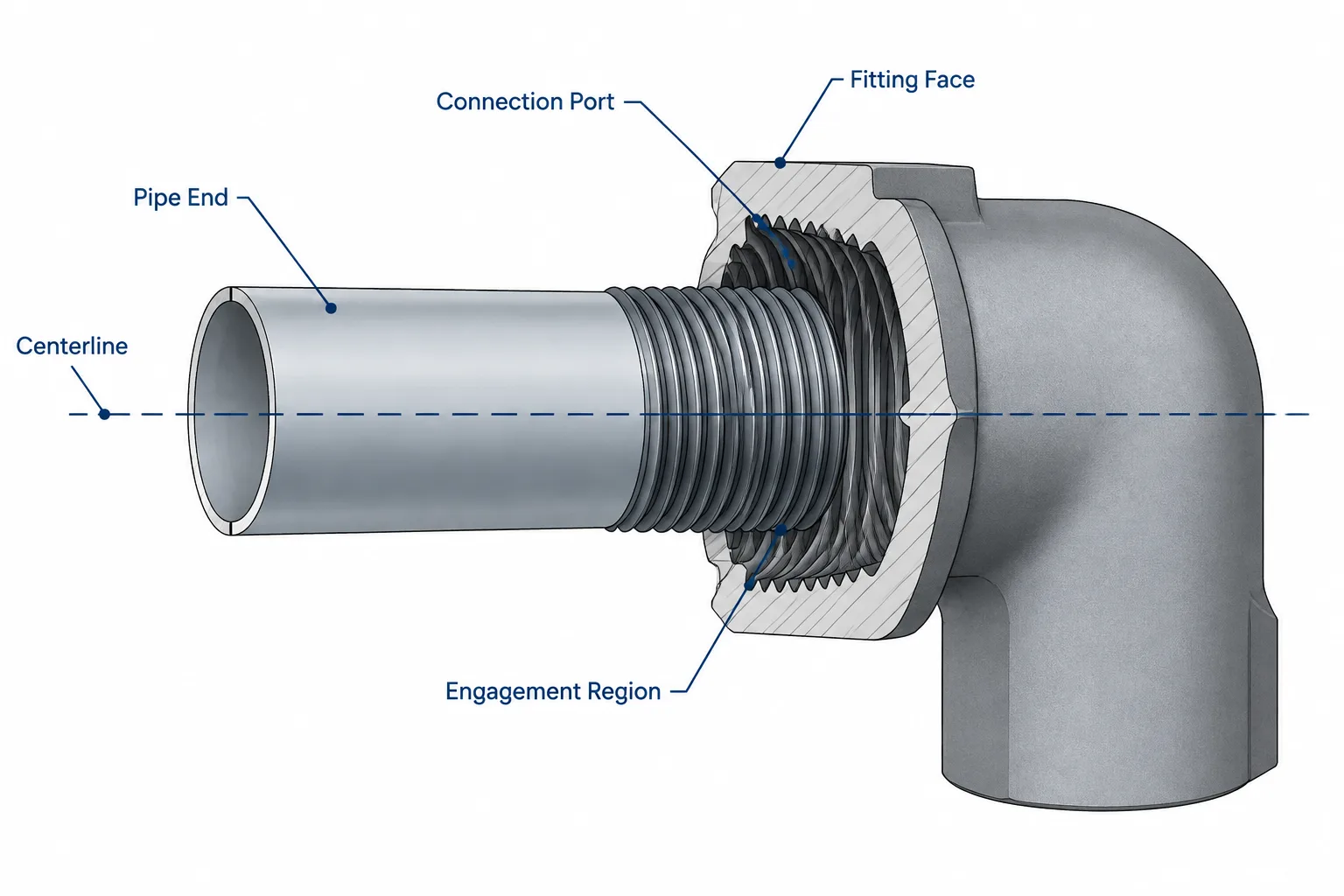
Threaded Pipe Joints in CAD: Engagement, Makeup, and Cut-Length Control
-
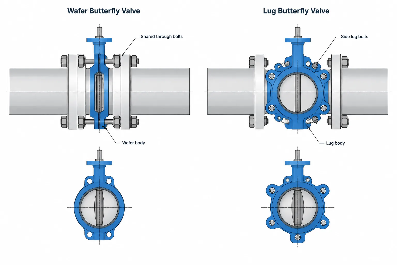
Wafer vs. Lug Butterfly Valves in Piping CAD: Bolting, Removal, and Layout Control