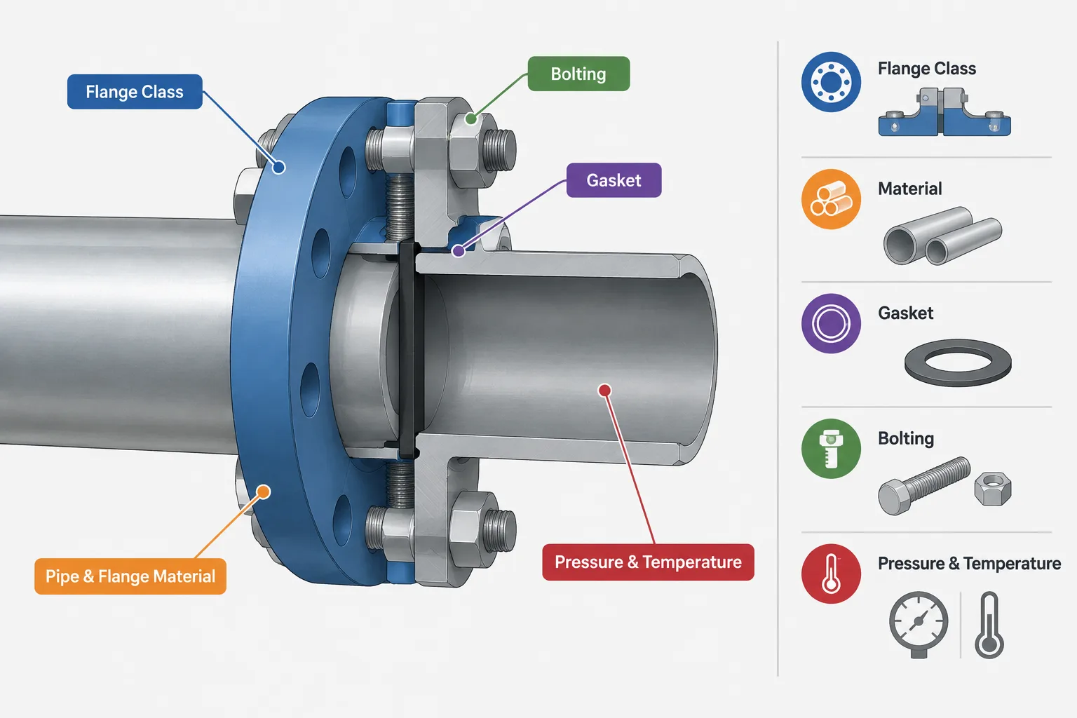
Flange selection cannot be completed by matching a class label to a pressure value. The designation must be interpreted within the governing rating system, then checked against the flange material, design temperature, design pressure, and limitations of the assembled joint.
This guide explains that distinction from both engineering and drafting perspectives. It also shows why flange metadata, physical geometry, gasket details, bolting, valve data, and connected-equipment requirements must remain coordinated throughout design, procurement, and model review.
A flange class designation is often mistaken for a direct pressure value. That shortcut can lead to incorrect component selection because class is not a universal maximum pressure expressed in pounds per square inch. It is a rating category used with a component standard, material group, and operating temperature to determine an allowable pressure–temperature rating.
This distinction matters when selecting flanges, flanged fittings, valves, gaskets, and bolting. It also affects how designers build piping specifications and how CAD users assign component data. A model that records only nominal pipe size and flange class may look complete while still lacking the information needed to verify the joint.
What Flange Class Actually Represents
Flange class identifies a standardized pressure–temperature rating category. The class designation places a component within a defined dimensional and rating system, but the designation alone does not state the component’s allowable pressure under every condition.
To determine an applicable rating, the user must consult the governing component standard using the correct material grouping and temperature. In general, allowable pressure changes as temperature changes because the strength and allowable stress basis of the material also changes.
This means that two flanges with the same class designation may not have the same allowable pressure if they are made from materials assigned to different rating groups. Likewise, the allowable pressure for one flange usually changes across its permitted temperature range.
Why Class Does Not Equal PSI
The numerical class label may resemble a pressure value, but treating it as a direct PSI limit ignores the rating method. A useful way to understand the relationship is:
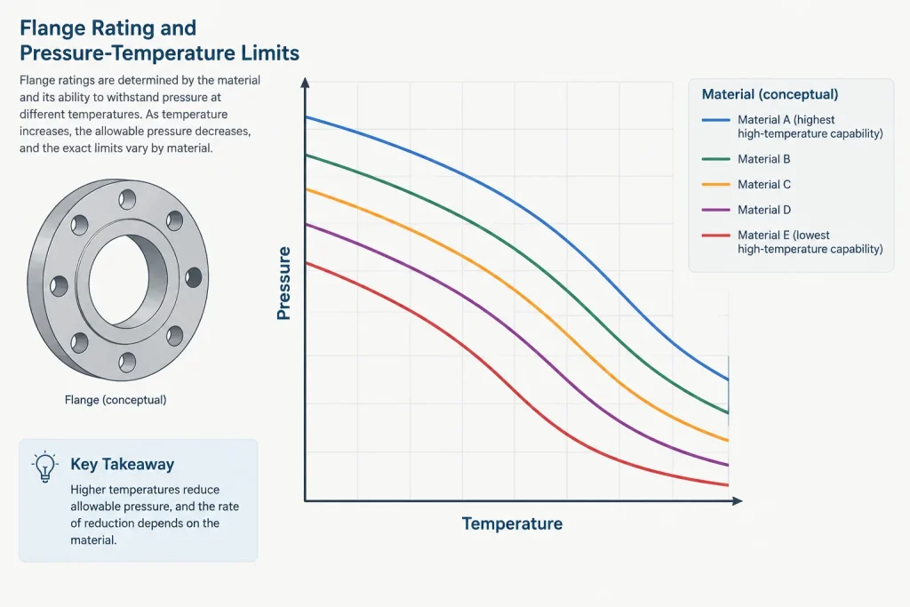
Flange class identifies the rating family; the pressure–temperature table provides the usable rating for the selected material and temperature.
The class designation also has a dimensional function. Within a particular flange type and nominal size, changing class may change features such as flange thickness, hub geometry, bolt-hole arrangement, bolt size, or facing details. The exact dimensional changes depend on the applicable standard and component.
As a result, increasing the class is not simply a documentation change. It can alter the physical envelope, joint stack-up, weight, bolting, and compatibility with adjoining equipment.
The Main Inputs Needed for Rating Verification
| Input | Why it matters | Typical source |
|---|---|---|
| Component standard | Defines the rating system, dimensional rules, and scope for the component | Project piping specification or component documentation |
| Material specification and grade | Connects the component to the correct material or rating group | Material class, purchase description, or manufacturer data |
| Design temperature | Determines which temperature point or permitted interpolation method applies | Line list, process design basis, or piping calculation |
| Design pressure | Provides the pressure demand that the selected rating must satisfy | Line list or approved design basis |
| Flange class | Identifies the candidate pressure–temperature category and associated geometry | Piping class or component selection |
| Special limits | May restrict the assembly below the flange body rating | Code requirements, specification notes, or manufacturer documentation |
The verification process must use consistent design conditions. Operating pressure is not automatically the correct value if the system’s design pressure is higher. Similarly, normal operating temperature may not represent the governing design temperature or another specified condition.
The Flange Is Only One Part of the Joint
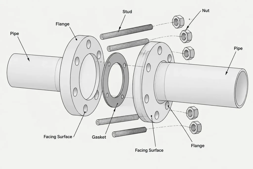
A pressure boundary assembled with flanges includes more than two flange bodies. The gasket, studs or bolts, nuts, flange facing, connected component, and assembly procedure all influence whether the joint is suitable.
Gasket compatibility
The gasket must be appropriate for the service, temperature, flange facing, and available seating load. A gasket designation should not be inferred from flange class alone. Different gasket constructions can have different chemical, thermal, handling, and seating requirements.
Bolting compatibility
Bolting material and dimensions must match the joint specification. Temperature limits, environmental exposure, corrosion protection, and required assembly load may affect the selection. A flange rating table does not replace verification of the bolting system.
Facing and joint type
Raised-face, flat-face, and ring-type-joint arrangements are not interchangeable descriptions. The mating faces, gasket type, and connected equipment must form a compatible assembly. CAD geometry should show the correct facing arrangement when that detail is relevant to layout, interference, or fabrication.
Connected component limitations
A flange may be attached to a valve, vessel nozzle, pump nozzle, lined component, nonmetallic component, or proprietary item. The complete connection is limited by its least capable applicable part, not automatically by the stamped or modeled flange class.
Flange Class Versus Piping Design Pressure
Design pressure describes a system design condition. Flange class describes a standardized component rating category. They serve different purposes and should not be entered into the same data field or used as synonyms.
A piping class may assign one flange class to a range of lines because it satisfies the project’s material and temperature envelope. That does not mean every line operates at a pressure corresponding to the class label. It means the project specification has selected a component category based on its design rules and standardization strategy.
Projects may deliberately standardize on a higher class than the minimum suggested by one operating case. Reasons can include specification consistency, availability, mechanical requirements, compatibility with equipment, cyclic service considerations, or future operating scenarios. The reason should come from approved engineering documentation rather than a CAD user’s assumption.
Do Valves Automatically Follow the Flange Rating?
Not necessarily. A flanged valve may use the same nominal class language as its connecting flanges, but its allowable pressure can also depend on the valve design standard, body material, temperature, seat or trim arrangement, end construction, and manufacturer limitations.
The end flanges must be dimensionally compatible with the piping connection, but end compatibility does not prove that every internal part of the valve is suitable for the service. Valve selection should therefore verify both connection data and the valve’s complete pressure, temperature, material, and service limitations.
A Practical Selection Workflow
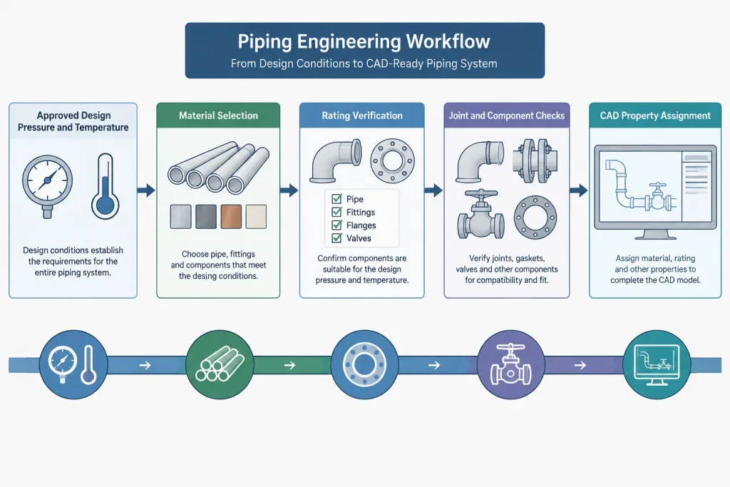
- Start with approved design conditions. Identify the governing design pressure and temperature rather than relying only on normal operating values.
- Confirm the piping material class. Determine which flange material, type, facing, class, gasket, and bolting the project specification requires.
- Identify the governing component standard. Do not combine dimensions from one component system with ratings from another without an approved basis.
- Locate the correct material grouping. Verify that the material specification and grade correspond to the rating data being used.
- Check the pressure–temperature rating. Confirm that the candidate class meets the required condition using the applicable rules.
- Review assembly limitations. Check gaskets, bolting, facings, valves, equipment nozzles, linings, coatings, and any manufacturer restrictions.
- Verify physical compatibility. Review bore, facing, bolt pattern, joint stack-up, outside envelope, access, and adjacent component geometry.
- Record the basis. Keep the class, material, standard, and relevant specification reference connected to the component record.
How to Represent Flange Class in CAD Data
Flange class should be stored as a controlled component property, not embedded only in a description that users must interpret manually. However, the model should not present the class field as if it were an allowable-pressure field.
Useful component properties may include nominal size, flange type, class, material specification, facing, component standard, piping class, commodity code, and manufacturer or catalog reference where applicable. The precise data structure depends on the project and software environment.
Geometry should also correspond to the selected class. Reusing a lower-class flange body and changing only its text attribute can create incorrect bolt patterns, thicknesses, hubs, clearances, and joint dimensions. Where generic geometry is used, it should be clearly identified and checked against verified project data before being relied on for fabrication or interference review.
Common Mistakes to Avoid
- Reading the class number as a universal PSI rating.
- Checking pressure without considering design temperature.
- Using a rating for the wrong material group.
- Assuming all components with the same class have identical allowable conditions.
- Changing a CAD class attribute without replacing the component geometry.
- Assuming matching bolt holes prove full joint compatibility.
- Ignoring gasket, bolting, facing, valve, or equipment limitations.
- Using operating conditions when the design basis requires more demanding conditions.
Key Takeaway
Flange class is a standardized rating and dimensional category, not a fixed pressure value. Proper selection requires the applicable component standard, material grouping, design temperature, design pressure, and complete joint specification. In CAD, the class designation should control both component metadata and verified geometry, while the engineering rating basis remains traceable to approved project documents.
Applying the Rating Basis Across Project Documents
A verified flange selection should remain consistent across the line list, piping material specification, component description, valve or equipment data, bill of materials, and CAD model. A class label appearing in every document does not establish consistency if the associated material, facing, standard, or design conditions differ.
Engineering selection
The engineering basis establishes the required design conditions and the rules used to select the component. The resulting flange class should be treated as an output of that evaluation rather than a substitute for it.
Specification and procurement
Purchase descriptions need enough information to identify the required component and compatible joint arrangement. Class by itself does not communicate the complete material, flange type, facing, dimensional system, or special project requirements.
Drafting and model review
Drafters should confirm that the placed component belongs to the approved piping class and that its geometry represents the intended connection. Review should include mating faces, bolt access, gasket space, adjacent equipment, and the overall joint envelope where those details affect layout.
Change management
A change in design temperature, material, connected equipment, or piping specification can require the rating basis to be reviewed even when the displayed class remains unchanged. Conversely, changing class can affect geometry, bolting, joint stack-up, procurement descriptions, and model clearances. The change should therefore be coordinated rather than handled as an isolated text edit.
A Useful Review Question
Instead of asking, What pressure does this class mean?, ask, What allowable pressure applies to this component material at the governing temperature under the applicable standard, and is every part of the joint compatible? That question keeps the class designation in its proper role and exposes missing selection data before it becomes a modeling, purchasing, or installation problem.
Frequently Asked Questions About Flange Class
Can flanges with the same class have different allowable pressures?
Yes. The applicable allowable pressure depends on factors that include the governing component standard, material grouping, and temperature. The shared class designation identifies a rating category, not one universal pressure limit.
Does selecting a higher flange class automatically make a joint suitable?
No. The proposed flange must still be checked for material, temperature, facing, gasket, bolting, connected-component, and dimensional compatibility. A higher class can also change the physical joint arrangement.
Can flange class be used to select a gasket by itself?
No. Gasket selection also depends on the facing arrangement, service, temperature, seating requirements, and project specification. The gasket and flange must be evaluated as parts of the same assembly.
Does matching the valve and flange class prove compatibility?
No. Matching class designations may support end-connection coordination, but the valve body, internal construction, materials, temperature limits, and manufacturer restrictions still require verification.
Why must CAD geometry be checked after a class change?
A class change may affect flange thickness, hub form, bolting, facing details, and the joint envelope. Editing only a model attribute can leave geometry that no longer represents the specified component.
What information should accompany flange class in component data?
Useful associated data includes nominal size, flange type, material specification, facing, component standard, piping class, and the approved component or catalog reference where applicable. Project procedures determine the required fields.