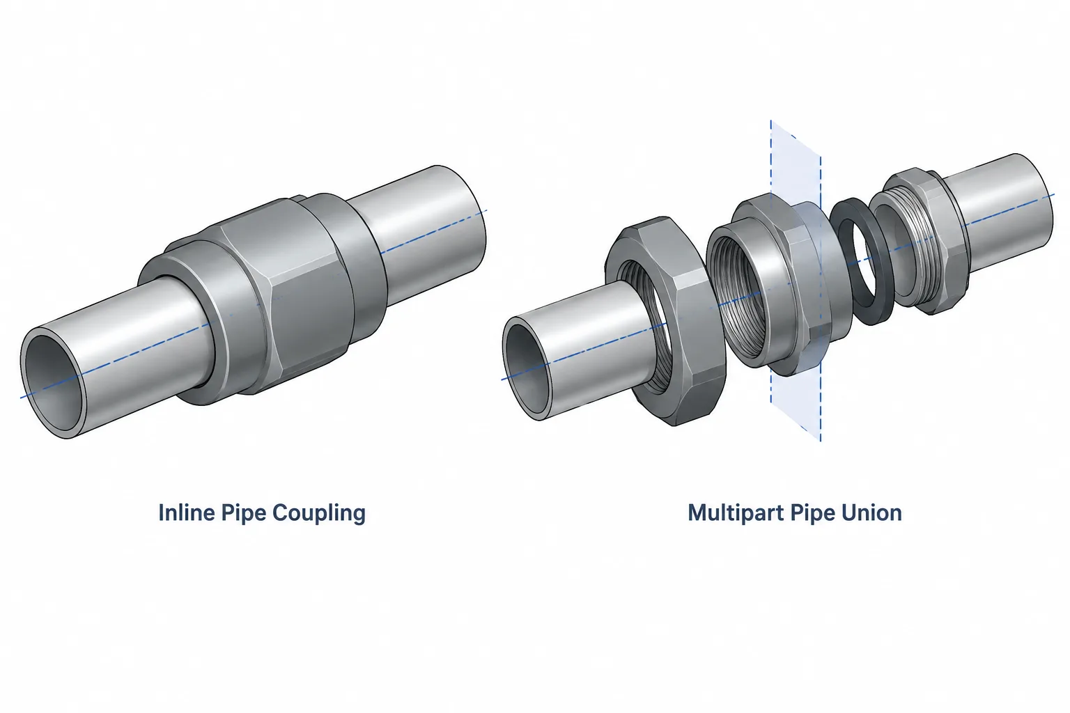
Choosing between a pipe union and a coupling is not merely a matter of selecting similar inline geometry. The fitting must communicate how the run is assembled, whether a planned separation point exists, and what access is needed for installation or maintenance.
This guide compares pipe unions vs. couplings in piping CAD from a practical design and drafting perspective. It explains what the model should show, which metadata should remain distinct, and why connection references must be verified before pipe cut lengths or fabrication information are released.
Pipe unions and couplings can look similar in a piping model because both are compact inline fittings. Their functions, however, are not interchangeable. A coupling primarily joins two pipe ends into a continuous run. A union also joins pipe, but it includes a separable joint that can be opened without rotating or cutting the adjoining pipe.
This distinction affects component selection, pipe cut lengths, maintenance planning, material takeoff, and CAD library management. A simplified model that treats every small inline fitting as a generic coupling can hide an intended break point or suggest that a joint can be dismantled when it cannot.
What Is a Pipe Coupling?
A pipe coupling is an inline fitting with two connecting ends. Depending on the piping system, those ends may be threaded, socket-weld, or another connection type. The fitting is generally intended to remain part of the assembled run rather than serve as a routinely opened mechanical joint.
A full coupling accepts pipe from both sides. Other coupling forms may perform specialized functions, such as changing size or closing one end, but those variants should be identified explicitly rather than represented as a generic full coupling.
A coupling does not normally provide a convenient way to separate a pipe run after both sides have been assembled. A threaded coupling may require one pipe or fitting to rotate during assembly and disassembly. A socket-weld coupling becomes part of a welded assembly and must generally be cut or otherwise removed through a planned fabrication procedure if the line must be separated at that location.
What Is a Pipe Union?
A pipe union is an inline fitting assembled from multiple pieces. Its central joint can be released so the connected pipe sections can be separated without turning the complete pipe runs. Common union arrangements include two end pieces, a central sealing interface, and a nut that draws the assembly together.
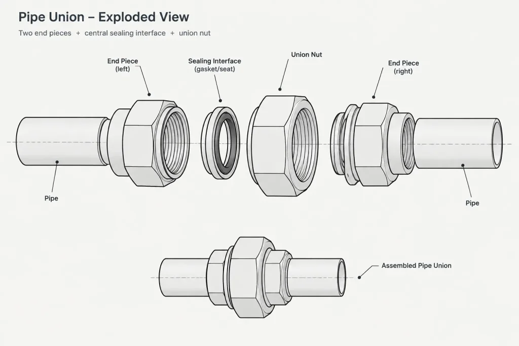
The sealing geometry and material details vary by union design. The joint may rely on matched metal seating surfaces, a replaceable sealing element, or another manufacturer-defined arrangement. A CAD symbol or generic solid should not be used to infer the actual seal type.
Unions are often placed where equipment, valves, instruments, strainers, or short piping assemblies may need to be removed. Their presence does not by itself establish that disassembly is safe. Isolation, depressurization, drainage, service hazards, and project requirements still control whether a joint may be opened.
Pipe Unions vs. Couplings at a Glance
| Design consideration | Coupling | Union |
|---|---|---|
| Primary purpose | Connect two pipe ends | Connect pipe while providing a separable joint |
| Typical disassembly | May require pipe rotation, joint removal, or cutting | Central joint can be released without rotating the adjoining runs |
| Number of functional pieces | Usually represented as one fitting body | Multipart assembly with a central closure |
| Maintenance role | Usually a permanent run connection | May act as a planned equipment or component break point |
| CAD representation | Simple inline body may be sufficient | Should remain visibly distinguishable from a coupling |
| Data requirements | Size, connection type, material class, and fitting form | Size, connection type, union design, material class, and sealing details where required |
Why the Difference Matters in Layout
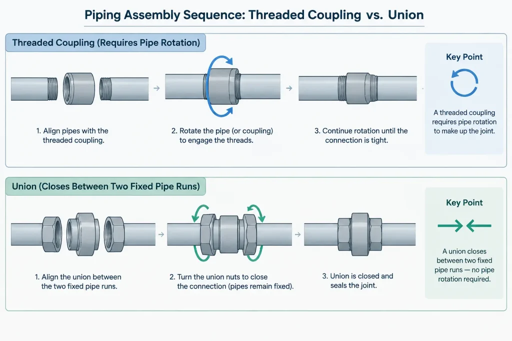
Pipe rotation during assembly
A threaded coupling can create an assembly-sequence problem. If both connected pipe sections are already restrained, neither side may be free to rotate into the coupling. A union avoids the need to rotate the complete adjoining run when its central joint is closed.
This issue is easy to miss in a finished CAD model. Geometry can be placed in its final position without showing how threaded pieces are actually screwed together. Designers should review the construction sequence, particularly around fixed equipment, wall penetrations, rigid supports, and branches connected at both ends.
Component removal
A union can help make an inline component removable, but one union is not automatically enough. The component may remain trapped by threads, sockets, flanges, supports, or surrounding geometry. The disconnection arrangement must allow the item to move far enough to clear its mating connections.
For example, a threaded item installed between fixed runs may require unions or other break joints arranged to release it without forcing adjacent piping. The correct layout depends on the item, connection sequence, available movement, and project specification.
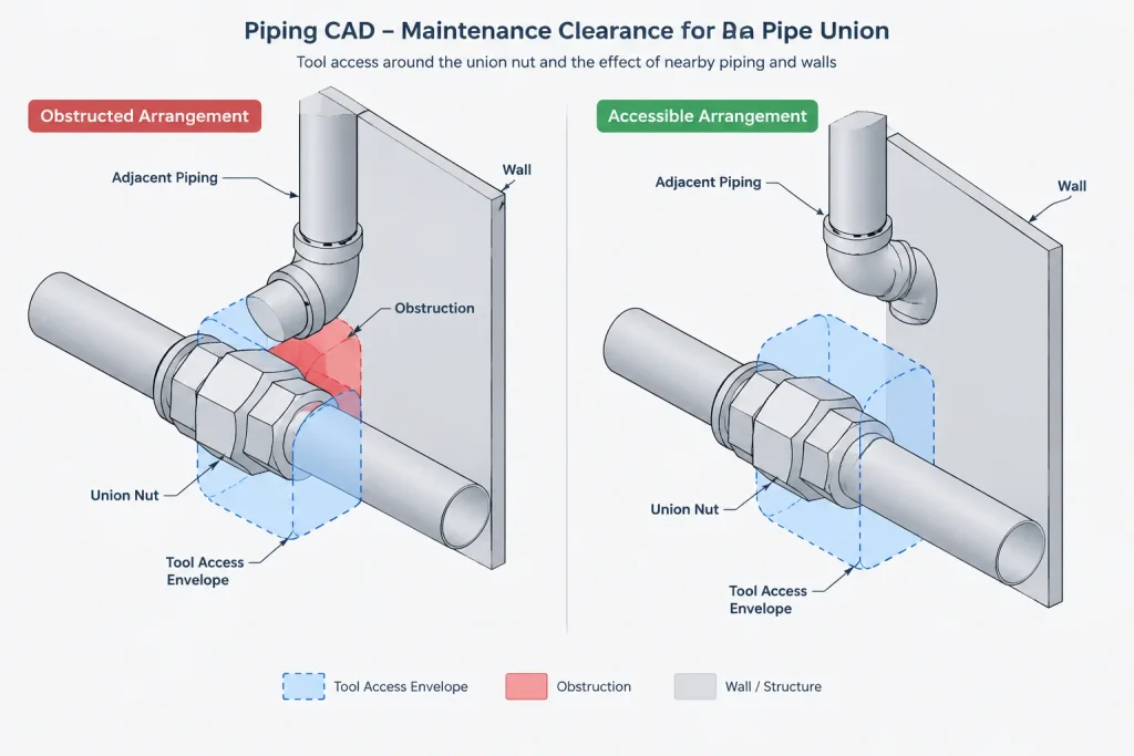
Access to the union nut
The union nut must be accessible to an appropriate tool. A union placed tightly against a wall, structural member, equipment casing, or neighboring pipe may be technically present but impractical to open.
CAD clearance reviews should consider the outside envelope of the union and the working space needed around it. Tool access is different from simple clash clearance: two objects can avoid geometric interference while still leaving insufficient room for maintenance work.
Connection Type Must Be Identified
Neither “union” nor “coupling” fully defines how the fitting connects to pipe. A component description should also state the applicable end connection. Threaded and socket-weld fittings have different fabrication and cut-length implications, even if their simplified model envelopes are similar.
- Threaded coupling: Pipe ends enter through threaded engagement. Final exposed pipe length depends on actual makeup, not merely the visible fitting length.
- Socket-weld coupling: Pipe enters sockets in the fitting body. Cut-length control depends on the applicable socket geometry and fabrication requirements.
- Threaded union: Threaded end pieces attach to the pipe or adjoining components while the central union joint provides separation.
- Socket-weld union: End pieces are welded to the adjoining pipe, while the union closure remains mechanically separable.
Mixed-end and manufacturer-specific arrangements may also exist. They should be modeled and described from verified component information rather than assumed from a generic family name.
Cut-Length and Dimension-Control Considerations
The visible overall length of a fitting is not necessarily the amount by which it shortens a pipe segment. Pipe cut length depends on the fitting’s connection reference points, engagement or insertion, assembly gaps where applicable, and the project’s fabrication method.
For threaded fittings, a CAD model should not treat the end face as though it were automatically the final pipe endpoint. Thread makeup can vary within the controlled assembly process. For socket connections, the model needs a defined insertion reference rather than an arbitrary point inside the fitting.
A union adds another important reference: the separable joint plane. This plane can help communicate where the assembly opens, but it should not be confused with either pipe endpoint. Useful CAD connection data may therefore include:
- Pipe connection points on both ends
- Component centerline
- End-face or engagement reference planes
- Union separation plane
- Overall maintenance envelope
- Flow direction only when the selected design is directional
How to Represent Unions and Couplings in CAD
The required model detail depends on the purpose of the deliverable. A schematic representation may only need a distinct symbol and tag. A coordinated three-dimensional model may need the correct overall envelope and connection points. Fabrication documentation may require verified component dimensions and explicit joint information.
Even in a low-detail model, unions should not be indistinguishable from couplings. A simple central break line, multipart body profile, or dedicated component class can preserve the functional distinction without modeling every thread or sealing surface.
Library metadata is equally important. Recommended properties include fitting type, nominal size designation, end connections, piping material class, component description, and source of dimensional data. If dimensions are preliminary, the model should communicate that status instead of presenting generic geometry as fabrication-ready.
Common Modeling and Documentation Errors
- Using a coupling where a break joint is required: The model connects correctly but does not support the intended assembly or removal sequence.
- Calling every multipart inline fitting a union: Similar external shapes do not prove that a component has a union-style separable joint.
- Ignoring threaded assembly order: Final geometry is modeled without checking whether the parts can be rotated into position.
- Providing no wrench clearance: The union nut is blocked by nearby piping, structure, or equipment.
- Deriving cut lengths from overall fitting length: Engagement and insertion references are omitted.
- Combining different end connections under one generic part: Threaded and socket-weld variants may require different geometry, descriptions, and fabrication treatment.
- Assuming a generic CAD block is project-approved: Selection and dimensions still require verification against the piping specification and approved product data.
A Practical Review Workflow
Begin by identifying why the inline fitting exists. If it only joins two pipe ends, a coupling may satisfy the intended function. If the location must provide a planned separation point, review whether a union or another removable-joint arrangement is appropriate under the governing specification.
Next, confirm the end connections and assembly sequence. Check whether either pipe section can rotate, whether welded sockets are involved, and whether the adjacent component can actually be extracted. Then verify dimensional data, connection points, sealing details where relevant, and access around the joint.
Finally, coordinate the model, drawing, and material list. The union or coupling should have the same identity across all deliverables. Preserving that distinction helps fabricators understand assembly intent and helps maintenance personnel recognize where a piping section was designed to come apart.
Using the Comparison During Model Review
A useful review should examine the fitting as part of an assembly rather than as an isolated CAD object. Follow the pipe in both directions and identify fixed equipment, rigid supports, branches, penetrations, and other features that may prevent rotation or axial movement. This reveals whether the modeled joint can actually be assembled and opened as intended.
Check the component identity across deliverables
The model object, drawing description, material list, and piping specification reference should consistently identify the component as a union or coupling. A visually correct model can still create procurement or fabrication errors if its part classification or description is wrong.
Separate design geometry from maintenance space
The physical fitting envelope is only part of the layout requirement. A union also needs usable access for operating the closure and enough movement to separate the adjoining assembly. Maintenance space may overlap temporarily with nearby operating space, so it should be reviewed intentionally rather than treated as ordinary clash clearance.
Record the source and status of dimensional data
Generic geometry may be adequate during early coordination, but it should be clearly identified as preliminary. Connection locations, engagement references, insertion references, and the separation plane should come from approved project or manufacturer information before the model is used for fabrication control.
CAD Quality-Control Checklist
- Purpose: Confirm whether the fitting only joins pipe or provides an intentional break point.
- End connection: Identify the actual connection method instead of relying on the family name.
- Assembly sequence: Verify required rotation, insertion, welding, and closure steps.
- Removal path: Check that the adjacent item can move clear after the joint is released.
- Access: Review tool approach and working space around a union closure.
- Connection references: Use verified engagement or insertion locations for cut-length control.
- Classification: Keep unions and couplings separate in CAD libraries and material reports.
- Data status: Mark generic or preliminary components so they are not mistaken for fabrication-ready parts.
Frequently Asked Questions
Can a coupling be used as a removable joint?
A coupling connects pipe, but it does not normally provide the same deliberate separation function as a union. Depending on its end connections, opening the run may require pipe rotation, removal of another joint, or cutting. The intended maintenance and assembly sequence should determine the component selection.
Why should a union look different from a coupling in a simplified CAD model?
The visual distinction communicates that the union contains a separable central joint. Without that distinction, reviewers may overlook a maintenance break point or incorrectly assume that a coupling can be opened in the same way.
Does adding a union make an inline component removable?
Not automatically. The component still needs an available removal path, sufficient movement, accessible connections, and a suitable isolation procedure. Adjacent supports and piping geometry can keep the item trapped even when a union is present.
Can overall fitting length be used directly for pipe cut length?
Not by itself. Cut-length control must account for the applicable engagement, insertion, end-face, and assembly references. These locations should be based on verified component data and the fabrication method.
What information should a union or coupling CAD object contain?
Useful properties include the fitting identity, nominal size designation, end connections, material class, dimensional-data source, and model status. A union may also need a defined separation plane and maintenance envelope.
Is a union always safe to open during maintenance?
No. A separable fitting does not establish safe working conditions. Isolation, depressurization, drainage, service hazards, site procedures, and project requirements must be addressed before the joint is opened.