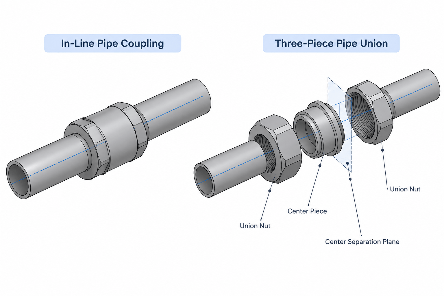
Choosing between a pipe union and a coupling is a functional layout decision, not simply a matter of selecting similar-looking CAD geometry. The fitting must represent the intended connection method, assembly sequence, disassembly point, and dimensional basis for adjacent pipe.
This guide explains how to distinguish pipe unions from couplings in models, isometrics, material lists, and maintenance reviews. Exact construction and dimensions must always be confirmed against the applicable piping specification and verified product data.
Pipe unions and couplings can occupy similar-looking positions in a piping layout, but they do not provide the same assembly or maintenance function. A coupling primarily joins two pipe ends. A union also joins two ends, but its multi-piece construction allows the connection to be separated without rotating the attached piping.
This distinction matters in CAD models, isometrics, material takeoffs, and maintenance reviews. Replacing a union with a generic coupling symbol may preserve the line centerline while removing the intended disassembly point. Conversely, adding a union where the piping specification does not permit one can create a material and sealing-interface conflict.
What Is a Pipe Coupling?
A pipe coupling is a fitting used to connect two pipe or component ends along a common axis. Common versions include threaded and socket-weld couplings, although the word coupling is also used for other proprietary or mechanical connection systems. The connection type must therefore be stated rather than inferred from the fitting name alone.
A conventional threaded coupling has internal threads at both ends. Installation generally requires rotating a pipe, nipple, or coupling as the threads are made up. A socket-weld coupling receives pipe into sockets at each end and is permanently joined by welding.
Once installed, neither type functions as a convenient mechanical break:
- A threaded coupling normally cannot be removed from between two fixed pipe runs unless other joints are loosened or a pipe section can rotate.
- A socket-weld coupling must be cut or otherwise destructively removed if the line must be separated at that location.
- The coupling itself does not create a detachable center joint.
What Is a Pipe Union?
A pipe union is a multi-piece fitting designed to create a separable in-line joint. A typical union includes two end pieces and a center nut that draws the mating seats together. The precise seat design, sealing method, material, and end connections depend on the selected product and piping specification.
The important layout feature is that the center connection can be released without turning the pipe attached to both ends. This makes a union useful near equipment or components that may require removal, particularly where rotating the connected piping would be impractical.

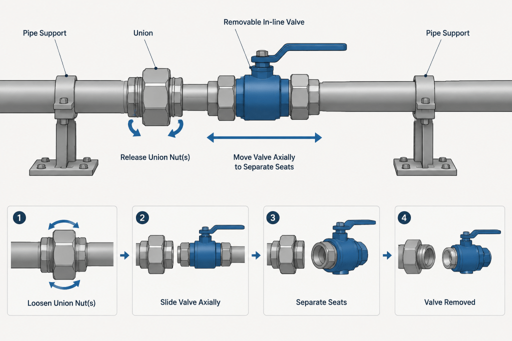
Opening the nut is only part of the removal process. The connected parts must still have enough freedom to move apart and clear the mating seats. A union should not be treated as eliminating every maintenance-clearance requirement.
Pipe Unions vs. Couplings at a Glance
| Design question | Coupling | Union |
|---|---|---|
| Primary purpose | Join two compatible ends | Join two ends and provide a separable joint |
| Typical construction | Single fitting body | Two end pieces with a center nut and mating seats |
| Disassembly | May require pipe rotation, joint cutting, or release elsewhere | Center joint can be opened without rotating both connected runs |
| CAD representation | One fitting with two connection ports | Assembly with end ports and an identifiable center break |
| Maintenance consideration | Usually not a planned removal point by itself | Often selected to support component or spool removal |
| Data verification | Confirm size, end type, material, and fitting dimensions | Also confirm seat, seal, nut envelope, and assembly dimensions |
This comparison describes general behavior, not universal product construction. Mechanical couplings, proprietary connectors, and specialty unions may work differently and should be modeled from verified project data.
Why the Difference Matters in CAD
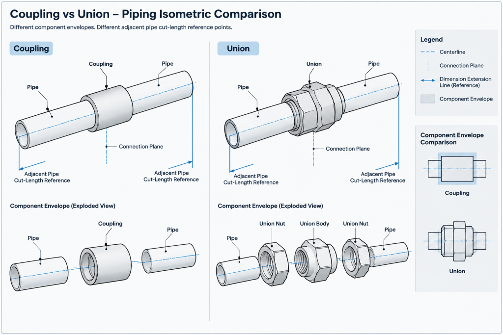
Component length affects adjacent pipe cuts
A union and a coupling should not be assumed to have the same end-to-end length. Even fittings with the same nominal size and end-connection family may have different dimensions by type, material, pressure designation, or manufacturer.
For an isometric or spool drawing, pipe cut length must be derived from verified fitting connection points. Do not substitute one fitting envelope for another and retain the original pipe cuts without checking the full dimension chain.
A union creates an intentional break point
The union center joint should be recognizable in the model or drawing. If a CAD object is represented as a plain cylindrical fitting, reviewers may mistake it for a coupling and miss the planned disconnection point.
The model does not need to reproduce every thread or internal seat. It should, however, communicate the assembly function through suitable geometry, a component description, an item code, or a drawing symbol consistent with the project convention.
End connections remain important
The detachable joint in the middle of a union does not define how its end pieces connect to the surrounding piping. Union ends may use connection forms such as threaded or socket-weld ends, subject to the selected specification and available product design.
Each CAD port should carry the correct end-connection data. Labeling the entire object only as a “union” is not enough for reliable specification checking or material extraction.
Modeling a Union as an Assembly
For schematic or low-detail work, a union can be represented by one intelligent component. For fabrication-oriented work, it is useful to understand the internal assembly even if the CAD system stores it as a single catalog item.
- Connection ports: Place the external ports at the actual pipe or component connection locations.
- Center break: Identify the plane where the two sides separate after the nut is released.
- Nut envelope: Show enough external geometry to support access and interference reviews.
- Axis control: Keep both ends coaxial unless a verified specialty design states otherwise.
- Insertion or engagement: Account for socket insertion or threaded engagement according to the applicable fitting data and project drafting method.
- Metadata: Record size, material, end type, specification reference, and component description without relying on shape recognition.
A simplified union block should not be scaled from a visual catalog image. Use verified dimensional data before issuing cut lengths, spool dimensions, or fabrication information.
Maintenance and Removal Planning
A union is often placed near a removable valve, instrument, trap, regulator, small pump connection, or other maintainable item. Its presence does not automatically make that item removable. The complete connection sequence must be reviewed.
Ask the following questions during layout:
- Can a wrench or other required tool reach and turn the union nut?
- Can the two sides move apart after the joint is released?
- Is there another rigid connection preventing axial or lateral movement?
- Will insulation, cladding, tracing, supports, or nearby steel obstruct access?
- Does the component being removed need a second break point?
- Can the released piping be supported safely during maintenance?
For example, installing one union next to a component held rigidly between two fixed connections may not provide enough freedom for removal. A workable arrangement may require another detachable connection, a removable spool, or a documented movement path. The correct solution depends on the system and project requirements.
Orientation and Drawing Clarity
A standard in-line union is usually symmetric about the pipe axis in a simplified model, but the two ends may not be interchangeable. Different end forms, seat designs, or material combinations can make orientation significant. Do not flip a catalog component merely because its external envelope appears symmetrical.
On an isometric, place the union callout so it is not confused with a threaded coupling or generic connector. Where the project symbol is highly simplified, reinforce it with an unambiguous bill-of-material description. On plans and elevations, show the nut envelope when it could affect access or clash clearance.
Bill-of-Materials and Specification Checks
A union is commonly purchased as an assembled fitting rather than as unrelated field-selected pieces. The bill of materials should follow the project catalog and purchasing convention. Splitting the nut and end pieces into separate line items without a specific procurement reason can create incorrect quantities or incompatible parts.
Before finalizing the model or material list, verify:
- Nominal size and compatible pipe size system
- End connection on each side
- Body and end-piece materials
- Seat or sealing arrangement
- Service and piping-specification acceptance
- Verified end-to-end and engagement dimensions
- Whether the item is a standard union, dielectric union, or another specialty assembly
A dielectric union should not be treated as a generic substitute for an ordinary union. It incorporates additional isolation features whose materials, configuration, and service limitations require separate verification.
Practical CAD Review Workflow
- Identify the intended function. Determine whether the fitting merely joins pipe or establishes a planned disassembly point.
- Check the piping specification. Confirm that the selected fitting type, material, and end connections are permitted.
- Use verified geometry. Set connection ports and overall length from approved project or manufacturer data.
- Recalculate adjacent pipe lengths. Do not carry over cut lengths from a coupling-based layout.
- Review assembly access. Check nut clearance, tool approach, insulation, and nearby obstructions.
- Test the removal sequence. Confirm that the connected component can move after the union is opened.
- Check the material output. Make sure the description distinguishes the union from a coupling and includes the required connection information.
Key Takeaway
A coupling is primarily a joining fitting, while a union is a joining fitting with a purpose-built separable center joint. That functional difference affects component selection, CAD geometry, pipe cut lengths, maintenance access, and bills of material. Model each item according to what it does—not merely according to its general outline—and verify the exact construction and dimensions before using the layout for fabrication or procurement.
Applying the Comparison to CAD Deliverables
The required level of model detail depends on the deliverable, but the component identity should remain consistent across the model, isometric, bill of materials, and maintenance documentation. A simplified shape is acceptable when its ports, description, connection data, and intended break point remain unambiguous.
Design teams should avoid using visible shape as the primary means of component identification. Similar external envelopes can conceal different end connections, engagement requirements, sealing arrangements, and removal behavior. Intelligent component data and controlled catalog descriptions provide a more reliable basis for checking and material extraction.
Separate Geometry Control from Functional Classification
Geometry establishes where the connected pipe terminates and how much space the fitting occupies. Functional classification establishes whether the item is a permanent joining fitting or an intended separable connection. Both are necessary: correct geometry alone does not communicate the maintenance purpose, while a correct description cannot compensate for inaccurate connection-port locations.
Coordinate Changes Across Documents
If a coupling is changed to a union, or a union is changed to a coupling, review more than the fitting tag. The change may affect adjacent pipe cuts, spool boundaries, material descriptions, connection callouts, access expectations, and the planned removal sequence. The revised item should be checked wherever piping geometry or component identity is reported.
Use a Controlled Review Question
A practical review prompt is: Can this fitting be assembled, identified, opened, and cleared in the arrangement shown? That question connects CAD accuracy with field assembly and maintenance intent without assuming that the fitting alone guarantees a workable removal path.
Frequently Asked Questions
Can a pipe union replace a coupling without changing the layout?
Not automatically. The union must be permitted by the piping specification, and its verified connection locations, end types, sealing arrangement, and external envelope must be checked. Adjacent pipe cut lengths may also require revision.
Does a union eliminate the need for maintenance clearance?
No. The nut requires access, and the separated sides still need enough movement to disengage and clear the mating surfaces. Supports, insulation, nearby equipment, and other rigid connections can restrict that movement.
Why should a union be identifiable in an isometric?
The union represents an intended separation point. If it appears as a generic coupling, reviewers and maintenance personnel may not recognize the planned break in the piping assembly.
Should a union be modeled as one component or several pieces?
Either approach may be appropriate under the project CAD convention. A single intelligent component can represent the purchased assembly, provided its external ports, center break, envelope, and metadata are controlled. More detailed assembly geometry may be useful when access or interference requires closer review.
Can union and coupling dimensions be treated as interchangeable?
No. Use verified dimensional data for the selected fitting. Do not retain pipe cuts or connection points from another fitting type merely because the nominal description or general outline appears similar.
Is every fitting called a coupling functionally the same?
No. The term can describe conventional threaded or socket-weld fittings as well as proprietary mechanical connection systems. The complete component description and connection method must be verified rather than inferred from the word coupling.