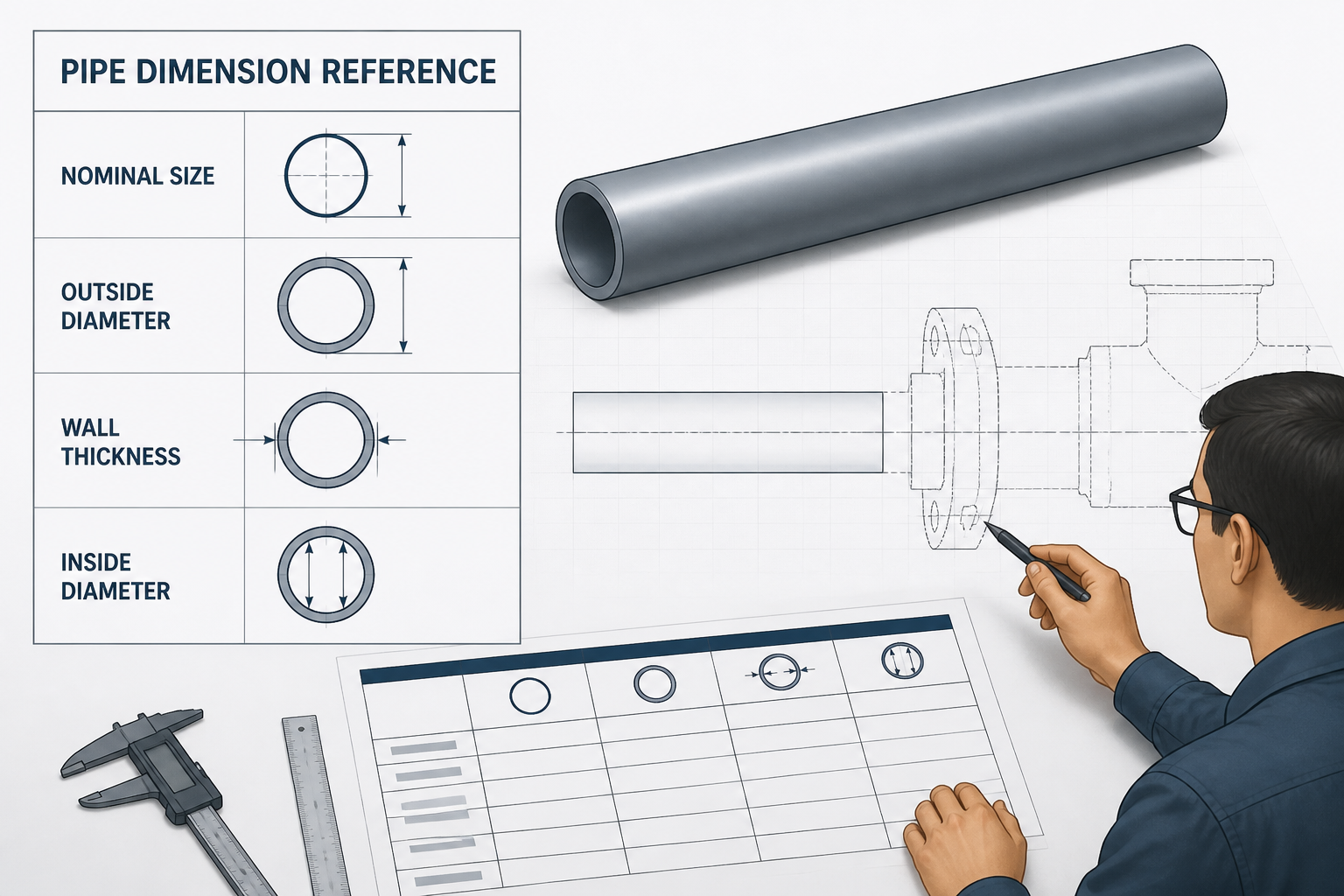
Pipe tables are compact but information-dense references. The key to using them correctly is to separate identification fields, such as nominal size and schedule, from measured dimensions, such as outside diameter, wall thickness, and inside diameter.
This guide provides a practical way to interpret a pipe table before using its data in CAD, drafting, estimating, fabrication, inspection, or coordination with fittings and flanges. Use the local table as the dimensional authority, and use project specifications and approved product information for material, service, and procurement decisions.
Pipe dimension tables are essential references for design, drafting, fabrication, estimating, and inspection. They can also be easy to misread. A table may show nominal pipe size, outside diameter, wall thickness, inside diameter, mass, and schedule in neighboring columns, even though each value serves a different purpose.

The most common mistake is treating a nominal pipe size or schedule designation as if it were a direct measurement. In practice, pipe identification and physical dimensions are related, but they are not interchangeable. A reliable workflow starts by separating the pipe’s naming system from the dimensions that must be drawn, modeled, checked, or purchased.
This guide explains how to read pipe schedule tables and how to use the information in a CAD or engineering reference workflow. It is intended to help you interpret local dimension pages; it does not replace the project specification, material requirements, governing design documents, or approved manufacturer information.
Start with the pipe identification
Before reading individual dimension columns, identify what the row actually represents. A complete pipe description commonly includes several separate pieces of information:
- Nominal pipe size: the standardized size designation used to identify the pipe family.
- Schedule or wall designation: the designation associated with a particular wall-thickness series.
- Material: the specified material grade or product category.
- Manufacturing or product standard: the document that controls the dimensional and product requirements.
- End condition: such as plain end, beveled end, threaded end, or another specified preparation.
These attributes answer different questions. Nominal size identifies the size family. Schedule helps identify the wall series. Material and product requirements determine whether a listed pipe is appropriate for a particular service or procurement package. End condition affects fabrication and connection details.
Understand what nominal pipe size means
Nominal pipe size, often abbreviated as NPS in U.S. customary practice, is a naming convention rather than a universal statement of the pipe’s measured inside or outside diameter. The nominal designation lets designers, fabricators, suppliers, and installers refer to the same size family consistently.
For many pipe sizes, the outside diameter remains associated with the size family while the wall thickness changes with the schedule. As the wall becomes thicker, the available internal opening changes even when the nominal size label does not. This is why a drawing or calculation should not use the nominal label as a substitute for the actual dimension needed.
For a practical reference workflow, use the nominal size to locate the correct row, then read the required physical dimensions from that row. If the task involves a connection, compare the pipe data with the applicable flange dimensions, fitting dimensions, and facing details rather than assuming that components with similar labels will automatically match.
Read schedule as a wall-thickness designation
A pipe schedule identifies a wall-thickness series within a nominal size system. It is not a pressure rating, material grade, or complete design qualification. Two pipes with the same nominal size can have different wall thicknesses when they have different schedule designations.
When reading a table, confirm that the schedule is in the same row as the nominal size you selected. Avoid carrying a schedule value from one size row into another. The relationship between schedule and wall thickness is not a simple visual scaling rule, so the authoritative local table should be used for the actual value.
Schedule is also different from a sheet or plate thickness. Pipe wall thickness is a product dimension associated with the pipe size and designation. If a fabrication note requires a particular wall, record the actual wall dimension and the identification designation where appropriate, rather than relying on a schedule label alone.
Know which dimension each column describes
| Table item | What it tells you | Typical use |
|---|---|---|
| Nominal size | The pipe size family | Searching, tagging, line lists, and component coordination |
| Outside diameter | The external cylindrical envelope | CAD modeling, clearances, clamps, supports, and sleeve checks |
| Wall thickness | The thickness of the pipe material | Section views, fabrication information, and engineering checks |
| Inside diameter | The internal flow opening | Flow-area work, lining coordination, and internal clearance review |
| Schedule | The wall-thickness designation | Identification and selection within a pipe size family |
| Mass or weight | The listed product mass basis | Material takeoff and preliminary handling or support studies |
Outside diameter is usually the controlling dimension for the physical envelope of a straight pipe. It matters when checking a pipe against a structural opening, insulation space, support clamp, guide, sleeve, or nearby equipment. Inside diameter is more relevant when the internal passage affects flow, cleaning access, instrumentation, or lining.
Wall thickness connects the two diameters conceptually, but the table remains the controlling reference for the published values. Do not round one column and then use the rounded result to recreate another column unless the engineering procedure specifically allows that approach.
Use the correct dimension for CAD and drafting
A CAD model should represent the purpose of the model. For a layout model, the outside envelope may be the most important pipe dimension. For a fabrication detail, the wall thickness, end preparation, centerline, and connection geometry may also be required. For a schematic or piping and instrumentation diagram, the nominal size and specification identifier may be sufficient, because the drawing is not intended to represent physical scale.
A practical modeling sequence
- Confirm the line or component identifier. Check the nominal size, schedule, material, and piping specification.
- Open the matching dimension reference. Select the correct product family before copying dimensions into a model.
- Set the outside envelope. Use the published outside diameter for spatial coordination and clash checking.
- Add the wall only when needed. Thin-wall visual models may not require a detailed solid, while fabrication or sectioned views may.
- Coordinate connected components. Check fittings, flanges, valves, gaskets, and weld details using their own dimension references.
- Label the model or drawing clearly. Preserve the nominal size and schedule or wall designation so another user can identify the source row.
For downloadable drawing work, this distinction is especially important. A pipe fitting reference may show a component’s end-to-end length, center-to-end dimension, or branch geometry, while the pipe table supplies the straight-pipe envelope. Both references are needed to create a coordinated detail.
Common mistakes when interpreting pipe tables
- Using nominal size as outside diameter: the label is a size designation, not a guaranteed measured diameter.
- Assuming schedule is pressure class: schedule describes a wall series; it does not replace a complete pressure design review.
- Mixing product families: pipe, tube, fittings, and hose may use different sizing conventions and should not be combined casually.
- Ignoring units: verify whether the table is presented in inches, millimeters, or another unit system before entering values into CAD.
- Reading across the wrong row: similar size labels or repeated schedule headings can make row selection error-prone.
- Using pipe dimensions for a fitting: elbows, tees, reducers, and caps have their own geometry and may change the overall layout.
- Forgetting wall loss or lining: internal coatings, liners, corrosion allowances, and fabrication conditions may affect the usable internal opening.
- Over-rounding values: rounded dimensions can create visible gaps or accumulated layout errors in detailed models.
A final verification checklist
Before publishing a drawing, exporting a CAD block, or using a table value in a calculation, verify the following:
- Is the nominal size taken from the correct pipe size system?
- Does the schedule or wall designation match the project line class?
- Are the outside diameter and wall thickness taken from the same row and product reference?
- Are the units consistent with the CAD file and drawing title block?
- Are connected fittings, flanges, valves, and gaskets checked separately?
- Does the model need a physical wall, or only a representative centerline and envelope?
- Have insulation, coating, lining, corrosion allowance, and fabrication details been addressed by the responsible project documents?
The most dependable way to read a pipe dimension table is to treat it as a coordinated set of identification and measurement fields. Use nominal size and schedule to find the correct product row, then use the specific outside diameter, wall thickness, and inside diameter required by the task. This simple separation reduces CAD errors, prevents mismatched components, and makes reference data easier for the next engineer or drafter to audit.
How to use this reference efficiently
When a table contains several similar-looking columns, begin with the row identity rather than the dimension you happen to need first. Confirm the pipe size system, schedule or wall designation, product family, and units. Then select the dimension that matches the task: outside diameter for the external envelope, wall thickness for section or fabrication work, and inside diameter for internal clearance or flow-related review.
This approach is particularly useful when moving between reference data and drawing geometry. A straight-pipe table does not define every dimension of a connected component. Elbows, tees, reducers, caps, valves, flanges, and gaskets require their own references. For coordinated layouts, compare the pipe data with the relevant pipe fitting dimensions and flange dimensions instead of inferring connection geometry from the pipe row.
Reference data versus design approval
A dimension table helps identify and model a product, but it does not by itself establish suitability for a service, pressure condition, temperature, material requirement, or complete design. Those decisions belong to the applicable project documents, product requirements, engineering calculations, and responsible reviewers.
For auditability, retain the source designation with the drawing, model, takeoff, or calculation input. Recording the nominal size, schedule or wall designation, product reference, and unit system makes it easier for another user to retrace the selected row and identify whether the correct physical dimension was used.
Frequently asked questions
Is nominal pipe size the same as the measured outside diameter?
No. Nominal pipe size identifies a standardized size family. The measured outside diameter must be taken from the applicable dimension row rather than inferred from the nominal label.
Does pipe schedule indicate pressure rating?
No. Schedule identifies a wall-thickness series. Pressure capability depends on the complete product, material, service conditions, design requirements, and applicable project or product documentation.
Which pipe dimension should be used for CAD clearance checks?
Use the published outside diameter for the pipe envelope, then account separately for insulation, coating, lining, supports, clamps, sleeves, and other project-specific additions.
Can a pipe table be used to model an elbow or tee?
Not by itself. The pipe table describes the straight-pipe data, while elbows, tees, reducers, caps, and other fittings have separate geometry references.
Why should inside diameter not be recreated from rounded values?
Rounding one dimension and using it to derive another can introduce discrepancies. When available, use the published value from the matching row and preserve the table’s units and precision in accordance with the project workflow.
What should be checked before using a table value in a drawing?
Verify the size system, product family, schedule or wall designation, units, selected row, connected-component references, and any project requirements affecting the modeled envelope or internal opening.