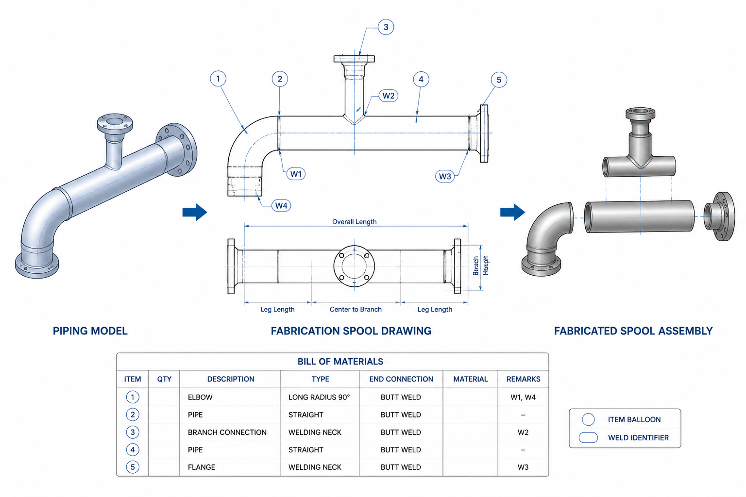
Creating a pipe spool drawing is a coordination task as much as a drafting task. The drawing must convert the approved piping arrangement into clear fabrication and installation information while preserving traceability to the line, components, welds, and project documents.
This guide follows a practical workflow from design-input review through spool splitting, component identification, dimensioning, bill-of-materials preparation, and CAD checking. Use it alongside the project piping specification, approved isometric, material-control procedure, and drafting standards.
A pipe spool drawing translates a three-dimensional piping arrangement into fabrication information that a shop can build and a field crew can install. It is more than a simplified isometric. A useful spool drawing identifies the pipe pieces, fittings, flanges, welds, dimensions, orientation, materials, and inspection points needed to control the work.
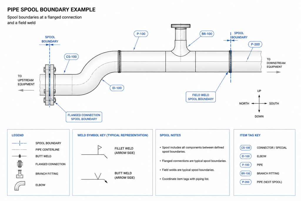
The drawing should be developed from approved design information, not from visual assumptions. Start with the piping isometric, line list, piping material specification, equipment connection information, and project drafting conventions. The goal is a drawing that removes ambiguity without repeating information that belongs in another controlled document.
What a pipe spool drawing is intended to show
A spool is a manageable fabricated section of piping. Its limits are usually defined by shop welds, field welds, flanged joints, threaded connections, or other intentional break points. A spool drawing records the geometry and component identity within those limits.
Depending on the project, one drawing may contain a single spool or several clearly separated spools. Each spool should have an unmistakable identifier, such as a spool number related to the line number and drawing package. The identifier must remain consistent across the material takeoff, weld map, inspection records, and installation documents.
- Geometry: pipe runs, elbows, branches, reducers, flanges, and orientation.
- Fabrication information: cut lengths, weld locations, joint numbers, and shop or field status.
- Component identity: item marks that connect the drawing to a bill of materials.
- Traceability: material descriptions, heat or batch tracking fields where required by the project.
- Installation information: field welds, temporary shipping breaks, lifting considerations, and connection orientation.
Step 1: Confirm the design inputs before splitting the line
Do not begin by drawing break points wherever the line appears convenient. First confirm that the source documents agree. Review the piping isometric against the line list and piping material specification. Check the line number, nominal pipe size, schedule or wall designation, material class, insulation status, fluid service notation, and designations for valves and specialty items.
Also review the connected equipment or nozzle information. A spool may fit geometrically in the model but still create an installation problem if a flange face, valve handwheel, instrument connection, or drain point is oriented incorrectly. Equipment connection details should be treated as controlled interfaces rather than inferred from the isometric alone.
This is where a link to a site guide on pipe dimensions and schedules can help readers distinguish nominal size from actual outside diameter, wall designation, and fitting dimensions. Those values should be taken from the project-approved reference data used by the design team.
Step 2: Decide where each spool starts and ends
Spool boundaries should support fabrication, transportation, handling, and field assembly. Common boundary conditions include:
- Flanged connections that can be assembled in the field.
- Field welds located where site access and alignment can be controlled.
- Connections to equipment, valves, specialty components, or prefabricated assemblies.
- Breaks needed to keep a fabricated section within practical handling limits.
- Locations selected to simplify weld inspection, coating, heat treatment, or internal cleaning.
Avoid placing a boundary through a component or at a location that makes the intended assembly sequence unclear. The selected break point should be visible in the model, identifiable on the drawing, and consistent with the fabrication plan.
When a boundary is a field weld, label it clearly. A field weld is not merely a drafting symbol; it affects installation planning, inspection, access, and often the order in which adjacent spools are erected. The final designation should follow the project’s weld numbering and documentation procedure.
Step 3: Build the component and weld structure
Once the boundaries are established, assign an item mark to every fabricated component. Typical items include straight pipe sections, elbows, tees, reducers, caps, flanges, blinds, valves, and branch fittings. The bill of materials should not rely on a reader counting graphical symbols.
Give each weld a unique joint number when the project requires weld traceability. The weld map should distinguish shop welds from field welds and should make the joint location unambiguous. Do not reuse a number within the same spool drawing package unless the project procedure explicitly allows it.
A good item structure makes later checking easier. For example, the drawing can identify a pipe segment by item mark, material description, nominal size, wall designation, and cut length, while the component schedule identifies a fitting by type, end preparation, rating or class where applicable, and material specification. The exact fields should follow the project template and material control system.
Step 4: Dimension the spool for fabrication and checking
Dimensions should describe how the spool is made and how it is checked. Use a combination of overall dimensions, center-to-center dimensions, face-to-center dimensions, and weld-to-weld dimensions as appropriate. Avoid dimensioning every graphical edge if a smaller set of references communicates the fabrication intent more clearly.
Dimension from stable references. Flange faces, pipe centerlines, branch intersections, and defined weld planes are usually more useful than arbitrary model edges. Where a dimension depends on a fitting’s center-to-end geometry, use the approved fitting data rather than estimating from the drawing scale.
Include orientation information for bends and branches. A spool can have correct lengths and still be impossible to assemble if an elbow rotation or branch direction is missing. Coordinate dimensions, north arrows, elevation references, or an orientation sketch can help when the spool has several changes of plane.
Never use the plotted scale as a substitute for a dimension. A drawing may be printed at a different size, and small graphical differences can be introduced by line weights, annotation settings, or view generation. If a dimension is important to fabrication or installation, state it explicitly.
Step 5: Show welds, end conditions, and preparation notes
The drawing should identify the end condition at every spool limit. A connection may terminate at a flange face, plain pipe end, bevel, threaded end, socket-weld fitting, grooved end, or another project-defined condition. The end symbol and note should agree with the material specification and fabrication procedure.
Weld symbols and notes should communicate the intended joint without forcing the fabricator to interpret the model. Use the project’s approved weld symbol convention, and separate general notes from joint-specific requirements. If a weld requires a particular inspection method, post-weld treatment, cleaning process, or acceptance record, reference the controlling project document rather than placing unsupported requirements on the spool drawing.
Branch connections deserve special attention. Confirm the branch type, orientation, attachment detail, and weld representation. A branch shown only as two crossing lines can be misread, especially in a crowded isometric view.
Step 6: Prepare the bill of materials and weld list
The bill of materials should reconcile with the drawing graphics. Every listed item should appear on the spool, and every component shown should have an item mark or an intentional explanation. Separate fabricated items from supplied valves, instruments, gaskets, bolting, and other components when the project’s procurement and installation responsibilities differ.
Include quantities, descriptions, size or wall designation, material identification, and relevant end or rating information only where those fields are controlled by the project data. Avoid copying a generic description that hides important differences between similar-looking components.
A weld list can include the joint number, location or connected items, weld category, shop or field status, and inspection or traceability fields. It should be possible to move from a weld symbol on the drawing to one row in the weld list without guesswork.
Step 7: Check the drawing in CAD before issue
Perform both a graphical check and a data check. In the CAD model, inspect the spool from several viewing directions. Confirm that branches, vents, drains, valve operators, flange faces, and support interfaces are not hidden or reversed.
- Verify that the line number and spool identifier are consistent in the title block, notes, and schedules.
- Check that item marks and weld numbers are unique and readable.
- Compare dimensions with the model rather than measuring the plotted sheet.
- Confirm that field welds and shop welds use the correct symbols and layer or color conventions.
- Check flange orientation, bolt-hole orientation where relevant, and clearance for assembly.
- Review branch direction, slope notation, vents, drains, and low-point or high-point features.
- Confirm that the bill of materials agrees with the modeled components.
- Remove construction geometry, duplicate annotations, and obsolete revision notes.
A useful internal reference can also connect this workflow to a guide on piping isometric checking and a separate explanation of flanged pipe connection review in CAD. These subjects support the spool review without replacing the project’s approved design documents.
Common pipe spool drawing mistakes
Unclear spool limits: The drawing does not show whether a flange, weld, or component belongs to the spool.
Missing orientation: The lengths are present, but elbow rotation or branch direction is not defined.
Mixed revision information: The drawing reflects one arrangement while the bill of materials or source isometric reflects another.
Uncontrolled dimensions: Fabrication dimensions are typed manually and no longer match the CAD model.
Overloaded views: Too many dimensions and leaders obscure the components and weld locations. Use additional views or a separate detail when needed.
Generic material descriptions: Similar components are listed without enough information to distinguish their material, end condition, or project item class.
Final review principle
A pipe spool drawing is successful when a fabricator can identify what to build, a checker can verify the geometry, and an installer can understand how the spool connects to adjacent work. Treat the drawing as a controlled interface between design, fabrication, inspection, shipping, and field installation. Use authoritative project data for dimensions and component selection, and use the CAD drawing to make the assembly intent explicit.
How to use this pipe spool drawing workflow
The source isometric communicates the overall routing and connectivity of a piping system. The spool drawing narrows that information into a controlled fabrication package. It should make the intended assembly understandable without requiring the fabricator or installer to infer missing orientation, connection, or weld information.
Keep geometry, data, and responsibilities aligned
A reliable spool drawing connects three related layers of information: the geometry shown in the drawing, the component and weld records, and the responsibilities assigned to the shop, field, inspection team, and material-control group. An attractive drawing can still be unusable if those layers disagree.
- Geometry: Show the physical arrangement, orientation, connection faces, branches, and relevant dimensions.
- Identification: Use consistent spool numbers, item marks, joint numbers, and line references.
- Execution: Distinguish shop work from field work and identify the interfaces that must be coordinated during installation.
- Verification: Check the drawing against the approved model and controlled project information before issue.
Use a review sequence that follows fabrication
Reviewing the drawing in the same order that the work will be performed often exposes omissions earlier. First confirm the source information, then verify spool boundaries and component identity. Next check dimensions, end conditions, weld information, and material records. Finish by reviewing the drawing from multiple directions and confirming that the bill of materials and weld list agree with the graphics.
Why revision control matters
Spool drawings often pass between design, fabrication, inspection, shipping, and field installation. A change to the route, component, weld location, or connection interface can affect several records at once. Revision status should therefore be checked across the drawing, source isometric, material list, weld documentation, and related installation records before release.
For drafting teams, this workflow also creates useful links to related references on pipe dimensions and schedules, piping isometric checking, and flanged pipe connection review in CAD. These references can provide terminology and checking context, but the project-approved documents remain the controlling source for design and fabrication decisions.
Practical issue checklist
Before issuing a spool drawing, ask whether an independent reviewer can answer these questions without relying on assumptions:
- What piping line and spool does the drawing represent?
- Where does the spool begin and end, and which interfaces are shop or field connections?
- Can every component and weld be matched to an item mark or joint record?
- Are orientation, branch direction, end conditions, and connection faces clear?
- Do the dimensions describe fabrication and checking rather than merely reflecting the plotted view?
- Does the bill of materials agree with the drawing and controlled material information?
- Does the revision status match the current approved design information?
Pipe spool drawing FAQs
What is the difference between a piping isometric and a pipe spool drawing?
A piping isometric primarily communicates the routed line and its relationship to the wider piping system. A pipe spool drawing focuses on a defined fabricated section and adds the component, weld, dimension, material, orientation, and installation information needed to control that section.
How should spool boundaries be selected?
Select boundaries using the approved fabrication and installation strategy. Consider flanged interfaces, field weld access, equipment and valve connections, transportation and handling, inspection, coating, cleaning, and the sequence for assembling adjacent work. The final boundaries should be visible and consistently documented.
Should every weld receive a joint number?
Use joint numbering when required by the project’s weld-control or traceability procedure. When numbering is used, each joint should be identifiable on the drawing and traceable to the applicable weld record or weld list.
What dimensions belong on a spool drawing?
Include the dimensions needed to fabricate, inspect, orient, and install the spool. Depending on the project, this may include overall, center-to-center, face-to-center, and weld-to-weld references. Use approved component data and project conventions instead of estimating from the drawing scale.
Why is orientation important on a spool drawing?
Correct lengths alone do not define a complete three-dimensional assembly. Elbow rotation, branch direction, flange orientation, slope, elevation relationships, and equipment interfaces may all affect whether the spool can be assembled as intended.
What should be checked before issuing the drawing?
Check the drawing against the approved isometric, model, line information, material specification, equipment interfaces, bill of materials, weld list, and revision records. Also inspect the spool from multiple viewing directions to find hidden, reversed, duplicated, or missing information.