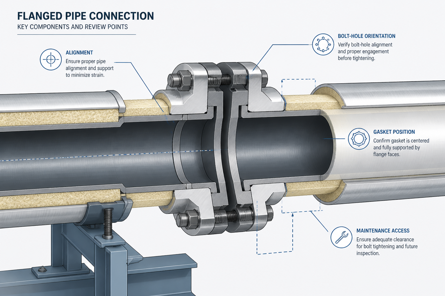
Checking a flanged pipe connection in CAD is more than confirming that two pipe centerlines meet. The model must communicate how the joint is oriented, assembled, inspected, and maintained. Small omissions—such as an incorrect bolt-hole rotation, an unclear gasket location, or blocked tool access—can remain hidden until fabrication or field installation.
This guide presents a practical review sequence for piping designers, CAD technicians, detailers, and engineers. Use it with the project piping specification, approved component data, and the relevant pipe dimensions and flange reference tables.
A flanged pipe connection can look correct in a plan or isometric view while still creating problems during fabrication, assembly, inspection, or maintenance. The flange may be rotated incorrectly, the gasket may be omitted from the detail, or nearby steel and insulation may block access to the bolting area. A reliable CAD review therefore needs more than a quick check of the pipe centerline.
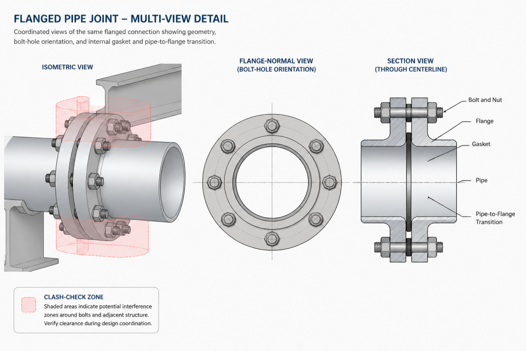
This workflow explains how to review a flanged connection as a complete assembly. It is intended for piping designers, detailers, CAD technicians, and engineers who work with pipe dimensions, fittings, flanges, and fabrication drawings. Always use the project piping specification, approved material list, applicable design requirements, and the selected flange manufacturer’s information when preparing a real project drawing.
What a flanged connection must communicate
A useful drawing should allow another person to understand how the connection is assembled without guessing. Depending on the drawing type, the model or detail should communicate:
- the pipe and flange nominal size, rating or pressure class, facing type, and material designation;
- the connection orientation and bolt-hole alignment;
- the gasket location and approximate installation space;
- the bolting arrangement and required access for installation;
- the relationship between the flange and connected equipment, valve, fitting, or spool;
- the required weld, thread, or other attachment detail; and
- any insulation, lining, fireproofing, coating, or removable-cover requirements that affect the connection.
These items do not all belong in every view. The important principle is that the drawing must contain enough information for the intended user: a modeler needs connection data, a fabricator needs clear joint and weld information, and a field crew needs orientation, access, and assembly information.
Start with the connection definition
Before checking geometry, confirm what the connection is supposed to be. A flange is not defined only by its outside shape. Its nominal size, pressure class or rating system, facing, bore, material, and attachment method all affect whether it can mate with the adjacent component.
Check the line list, piping class, equipment nozzle schedule, valve data, or other approved project source. Do not infer a flange class from its appearance in a general arrangement drawing. Similarly, do not substitute a dimension from a different flange type simply because the bolt circle appears similar in a small CAD view.
A useful model-data checklist includes:
- nominal pipe size and pipe wall or schedule designation;
- flange type, such as weld neck, slip-on, socket-weld, threaded, blind, or lap-joint arrangement;
- facing and gasket style;
- material and specification designation;
- bolt and nut material or project bolting category;
- insulation, lining, and corrosion allowance assumptions; and
- the source or revision of the dimensional data used in the CAD block or family.
For dimension verification, use the site’s relevant flange reference tables together with the project-controlled source. Reference tables help identify the correct dimensions, but they do not replace project specifications or approved vendor data.
Review flange orientation and bolt-hole rotation
Flange orientation is one of the most common sources of drawing errors. In a three-dimensional model, a flange can be connected to the correct pipe axis while its bolt holes are rotated into an unusable position. This is especially easy to miss when the connection is viewed only in an isometric projection.
Review orientation in a view normal to the flange face. Confirm whether the project requires a particular bolt-hole position, such as a hole centered on a vertical or horizontal reference line. The governing requirement may come from equipment vendor documents, piping design practice, access constraints, or a project drafting standard.
Then inspect the connection in at least one perpendicular view. Look for:
- bolt holes aligned with the mating flange;
- consistent flange-face orientation at both ends of the joint;
- valve handwheels, actuators, vents, drains, and instruments in their intended positions;
- clearance between bolts and nearby pipe, steel, supports, or equipment; and
- an orientation that remains understandable in the fabrication or installation view.
If the CAD system uses connection ports or intelligent flange objects, verify that the port rotation matches the visible geometry. A correct-looking solid with incorrect connection metadata can create downstream errors in automated spool generation, bill-of-materials extraction, or clash checking.
Check gasket space and flange-face condition
The gasket is part of the joint, even when it is not modeled as a solid. A drawing should make the gasket location clear through a symbol, note, detail, or assembly convention appropriate to the project.
Check that the two flange faces are separated by the intended joint arrangement rather than accidentally modeled as touching or overlapping. The drawing does not need to show a fabricated gasket thickness unless the project requires it, but it should not imply an impossible assembly. Pay particular attention to connections near equipment nozzles, removable spool pieces, and blind flanges.
Also confirm the facing designation. Raised-face, flat-face, ring-type, and other facing arrangements can require different gasket and bolting details. Avoid treating the flange outline alone as proof of the facing type; the model properties and drawing notes should agree.
Evaluate bolt installation and maintenance access
A connection may pass a basic clash check while still being difficult to assemble. CAD review should consider the space needed to insert, remove, and turn the bolting tools, not just the final envelope of the installed hardware.
| Review area | Question to ask |
|---|---|
| Bolt insertion | Can the bolt be inserted from the required side without passing through steel, insulation, or equipment? |
| Nut access | Is there room to position and hold the nut during assembly? |
| Tool access | Can the specified tightening method be used in the available space? |
| Removal path | Can bolts be removed later without dismantling unrelated piping or structures? |
| Inspection | Can the joint, gasket area, and bolting be visually inspected as required by the project? |
Access is often restricted by pipe racks, platform beams, cable trays, equipment skirts, valve operators, and insulation thickness. A two-dimensional plan may hide these restrictions, so review the connection in the coordinated three-dimensional model when available.
Check the pipe-to-flange transition
The connection between the pipe and flange should match the selected flange type. For example, a weld-neck flange needs a suitable butt-weld transition, while a socket-weld or threaded arrangement has different modeling and detailing implications. The CAD representation should not show a generic flange attached to every pipe type without regard to the actual joint.
Look for an accurate bore transition, especially where the internal passage affects flow, lining, or inspection. The outside model may be sufficient for a layout drawing, but fabrication documents may need additional information about weld preparation, internal alignment, or fitting details.
When the flange is connected to a valve or equipment nozzle, compare the pipe bore and flange bore assumptions with the approved component data. Do not use a simplified CAD block as the sole source for final fabrication dimensions.
Use section views and controlled simplification
Section views are valuable because they reveal problems hidden in plan and isometric views. A section can show the pipe wall, flange bore, gasket position, facing, weld, lining, and insulation relationship in one place.
Use simplified graphics carefully. A general arrangement drawing may omit bolt threads, gasket material, or small edge details for readability. That simplification is acceptable when the drawing includes a clear note or references the appropriate detail. It becomes risky when omitted information changes how the joint would be fabricated or assembled.
Maintain a clear distinction between:
- model geometry used for coordination;
- symbolic geometry used for readable drawings; and
- manufacturing geometry used for fabrication or purchasing.
This distinction is particularly important when exporting DWG files or sharing blocks between CAD platforms. A block that is adequate for routing may not contain the information needed for a spool drawing.
Perform a final drawing and data audit
Before issuing the drawing, compare the visible detail with the associated attributes, bill of materials, and notes. A flange can be dimensionally correct while the title, tag, material code, or connection description is wrong.
Use this final audit:
- Confirm that the flange type and facing agree in the model, note, and material list.
- Confirm that the mating components use compatible nominal size and connection definitions.
- Check bolt-hole orientation in a flange-normal view.
- Review gasket indication and flange-face separation.
- Check installation, inspection, and maintenance access.
- Verify that weld, thread, lining, coating, and insulation notes are present where required.
- Regenerate the drawing after any model rotation or connection change.
- Record the data source and revision used for the dimensional component.
A disciplined flange review prevents many errors before they reach fabrication or the field. The most effective workflow combines authoritative dimensional data, accurate connection metadata, coordinated three-dimensional review, and clear two-dimensional detailing. Use flange tables for controlled dimensions, use project documents for design intent, and use CAD views to test whether the complete joint can be understood, assembled, inspected, and maintained.
How to use this CAD review workflow
Review the connection in the same order that a real project decision is made: identify the required connection, confirm the geometry, test assembly access, and then audit the drawing information. This helps separate a visually acceptable model from a connection that is actually ready for coordinated design documentation.
Begin with design intent, not the visible solid
Start by identifying the controlled source for the connection definition. The line list, piping class, equipment data, valve information, or approved vendor document should establish what the CAD component represents. This is especially important when a simplified block or library part resembles several flange arrangements.
Use the site’s pipe dimension references and flange tables to check dimensional identity, but keep project-controlled information as the governing source. A reference table can help detect an incorrectly selected component; it cannot establish project design intent by itself.
Review the joint as an assembly
After confirming the connection definition, inspect the joint from views that expose orientation, mating faces, gasket placement, and the pipe-to-flange transition. The key question is not simply whether the parts occupy the same location. Ask whether another person could understand how the parts are brought together and whether the model agrees with its connection properties.
For coordinated layouts, a simplified model may be appropriate. For fabrication or purchasing documentation, the required level of detail is different. Keep routing geometry, drawing symbols, and manufacturing information clearly distinguished. Related resources on pipe fittings and CAD and DWG references can help maintain consistent component representation across drawings.
Test access before issuing the drawing
Clash-free geometry does not automatically provide usable installation access. Review the space around the joint for bolt insertion, nut positioning, tightening tools, inspection, and later removal. Consider nearby structural steel, supports, equipment, cable trays, valve operators, insulation, and access platforms as part of the connection review.
When the model is coordinated in three dimensions, use it to test the practical work envelope around the flange. Then confirm that the issued plan, elevation, section, or isometric views show the constraints that matter to the intended user.
Finish with a model-to-document check
Before release, compare the visible connection with its attributes, notes, material information, and bill of materials. Pay special attention to changes made by rotating a flange, replacing a library component, changing a facing selection, or updating a connected valve or equipment nozzle. Regenerating views and checking connection metadata after such changes helps prevent inconsistencies between the model and the drawing.
Frequently asked questions
Why can a flanged connection look correct in an isometric view but still be wrong?
An isometric view can hide bolt-hole rotation, flange-face mismatch, blocked access, or an incorrect connection property. Review the joint in a view normal to the flange face and in additional coordinated views.
Does the gasket need to be modeled as a solid?
Not always. The required representation depends on the drawing purpose and project convention. The important point is that the gasket location and applicable joint arrangement are communicated clearly and do not imply that the flange faces are incorrectly touching or overlapping.
What should be checked around the bolts?
Check whether bolts can be inserted and removed, whether nuts can be positioned and held, whether the specified tightening method can be used, and whether the completed joint can be inspected. Nearby steel, insulation, equipment, supports, and operators can restrict these activities.
Can a generic CAD flange block be used for fabrication drawings?
A generic block may be adequate for routing or general coordination, but it should not automatically be treated as fabrication data. Confirm flange type, facing, bore, attachment method, material information, and project-controlled dimensions before using the component for detailed documentation.
Why are connection attributes important if the solid geometry is accurate?
Connection metadata can control automated spool generation, bill-of-materials extraction, clash checking, and drawing output. A visually accurate solid with incorrect metadata can produce downstream errors even when the displayed geometry appears acceptable.