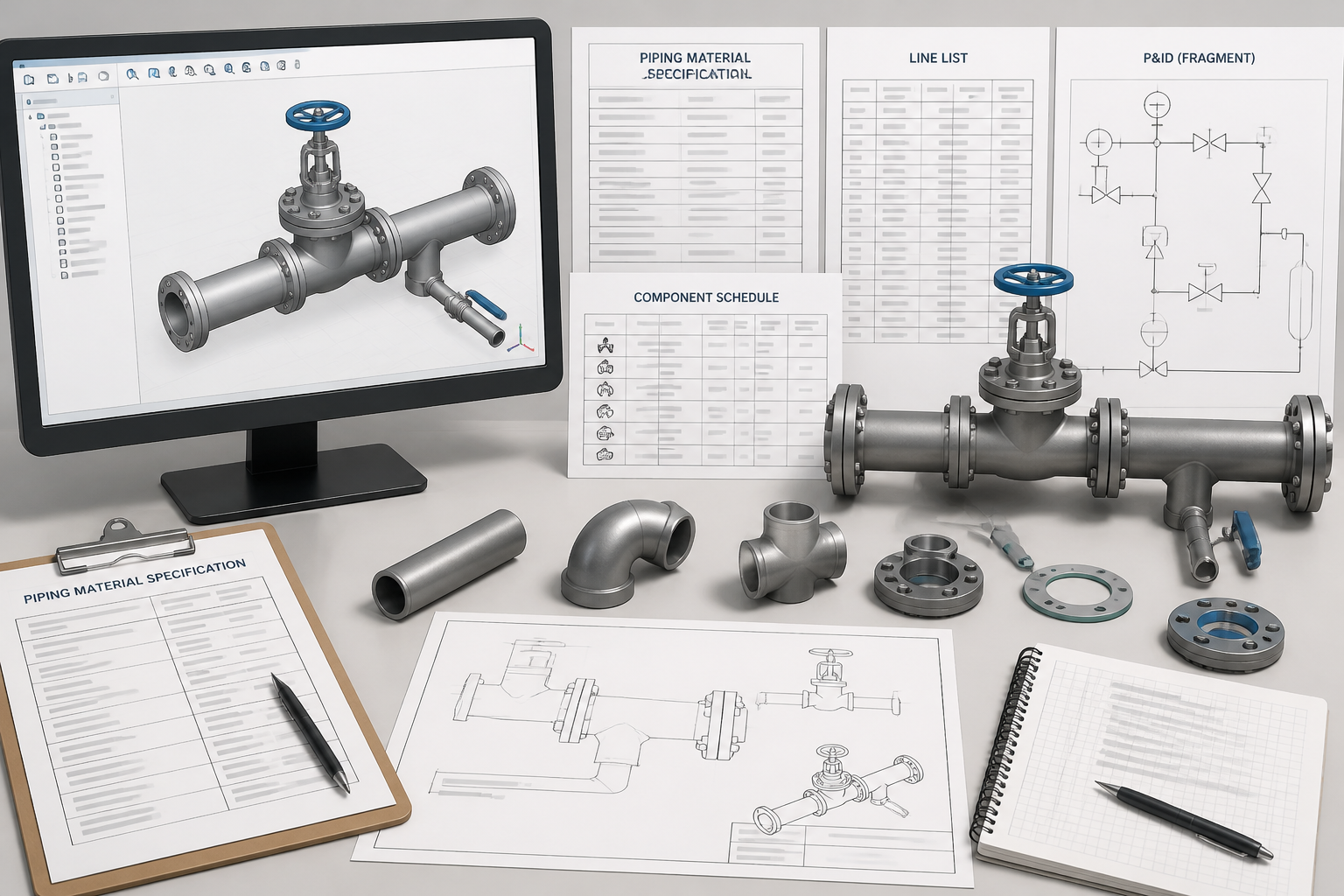
Before a pipe route becomes a CAD model, the designer must establish which components are permitted on that line. A piping material specification provides that selection framework, but it must be read together with the line list, P&ID, project legend, and applicable design requirements.
This guide is useful for piping designers, CAD drafters, and reviewers who need to connect project documentation with accurate model and drawing content. It focuses on the reasoning behind component selection so that a visually complete drawing does not conceal an incorrect material class, connection type, or branch arrangement.
A piping material specification is one of the most important documents behind a piping layout, isometric, and fabrication drawing. It defines the permitted components for a service or line class, while the drawing shows where those components are arranged. Reading the specification correctly helps a designer avoid mismatched flanges, incorrect branch connections, incompatible materials, and details that cannot be fabricated or maintained.
This guide explains a practical way to interpret a piping material specification before creating or checking CAD work. It is intended as a drafting and design reference, not as a substitute for the project specification, approved piping class, engineering calculations, or applicable code review.
What a piping material specification does
A piping material specification, often called a piping class or line class, establishes the rules for selecting piping components within a defined service. It may identify the pipe material, wall designation, fittings, flanges, valves, gaskets, bolting, branch connections, corrosion allowance, joining method, and limitations on use.
The specification does not replace a line list or P&ID. A line list identifies the individual line and its operating information. A P&ID communicates process intent and major equipment or valve relationships. The material specification provides the component-selection framework that allows those requirements to be turned into a detailed model or drawing.
For drafting work, this distinction is essential: the drawing should not be used to guess the material class. Confirm the line designation from the project documents first, then use the corresponding specification to select and represent components.
Start with the line identification
Before opening a component table, decode the line number or line designation. Project line numbering systems vary, but they commonly contain information related to size, service, sequence, insulation, tracing, or material class. The exact meaning must come from the project legend or line-list conventions.
Check the following items:
- Line size: Confirm the nominal size shown in the line list, P&ID, or model.
- Service: Verify that the line carries the fluid or utility associated with the selected class.
- Material class: Identify the piping specification assigned to the line.
- Pressure and temperature information: Use the project source documents to confirm the design basis; do not infer it from the line number alone.
- Insulation, tracing, and special notes: These can affect clearances, support details, valve access, and the appearance of the CAD model.
If the line number and the material class appear inconsistent, stop and resolve the discrepancy before drafting. A clean-looking model can still be wrong if it was built from the wrong class.
Read the specification in layers
Material specifications are easier to understand when read from general rules to individual components. A useful sequence is to review the document in five layers.
| Layer | What to check | CAD consequence |
|---|---|---|
| Scope and service | Where the class applies and what it excludes | Confirms whether the class belongs on the selected line |
| Pipe and tube | Material, manufacturing form, wall designation, and end preparation | Controls the modeled pipe and connection assumptions |
| Fittings and branches | Elbows, tees, reducers, caps, outlets, and permitted alternatives | Controls geometry, routing, and branch representation |
| Flanges, gaskets, and bolting | Facing, pressure class, gasket type, and bolting material | Controls flange selection and connection details |
| Valves and special components | Body materials, ends, trim, operators, and restrictions | Controls symbol, envelope, access, and bill-of-material data |
This layered approach prevents a common mistake: jumping directly to an elbow or flange row without first confirming the service, pipe material, and connection philosophy.
Do not confuse pipe schedule with material class
Pipe schedule and piping material specification describe different things. A schedule or wall designation describes a pipe wall category. A material specification defines a broader component-selection system that may include pipe, fittings, flanges, valves, gaskets, and bolting.
A piping class may permit different wall designations for different sizes or component types. It may also include notes that modify the general component table. For that reason, selecting a pipe from a dimension table does not automatically identify the correct fittings or flange rating.
Use the project’s pipe dimension and schedule reference to verify geometric data such as outside diameter and wall-related dimensions. Use the piping material specification to verify whether that pipe and its connected components are permitted for the line.
Check connection types before modeling
Connection type is a major source of drafting errors. A specification may distinguish among butt-weld, socket-weld, threaded, flanged, grooved, or other connection arrangements. These are not interchangeable graphic treatments.
For each connection, confirm:
- Whether the pipe end and fitting end use the same joining method.
- Whether a transition component is required between different end types.
- Whether the flange is integral, welded, threaded, or attached through another fitting.
- Whether the joint requires a gasket and bolting representation.
- Whether the connection has a special orientation or access requirement.
In a 3D model, the connection type can affect weld locations, spool breaks, flange faces, insulation gaps, and fabrication information. In a 2D drawing, it can affect weld symbols, end-condition notes, and the interpretation of the bill of materials.
Review branch connections separately
Branch connections deserve a separate check because they are often governed by more detailed rules than ordinary elbows and tees. A material specification may permit a reducing tee, a forged branch fitting, a welded outlet, or a branch arrangement subject to size and service limitations.
Do not select a branch component solely because its shape appears to fit the drawing. Check the permitted branch type, the connection ends, the material, and any project notes. Then verify that the branch location and orientation agree with the P&ID and the physical layout.
When the specification provides alternatives, document the selected option in the model, isometric, or component data. Otherwise, a later reviewer may not know whether the choice was intentional or accidental.
Use notes and exceptions as controlling information
The notes section is often more important than the main component table. Notes may limit the use of a valve, require a particular gasket family, prohibit a material combination, identify an alternative component, or direct the designer to another project document.
Read notes in context. A general component row may appear acceptable until a note restricts it to a particular service, temperature range, size range, or installation condition. Exceptions can also apply only to certain branches, dead legs, vents, drains, or equipment connections.
In CAD, record important exceptions in a practical way:
- Add a clear component description or classification to the model.
- Use a drawing note when the exception cannot be communicated through the graphic alone.
- Keep the line class and selected component data synchronized with the bill of materials.
- Flag unresolved substitutions for engineering review instead of silently changing the model.
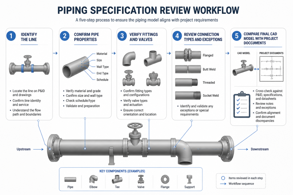
A practical CAD verification workflow
After reading the specification, use a repeatable check before releasing a drawing or model.
- Identify the line: Confirm line number, size, service, and assigned material class.
- Set the pipe properties: Apply the correct material, wall designation, and end condition to the CAD object or project database.
- Check every component: Review fittings, flanges, valves, branches, gaskets, and bolting against the class.
- Check transitions: Look for reducers, material changes, flange changes, and connection-type changes.
- Review notes: Apply exceptions and special requirements before generating the isometric or bill of materials.
- Compare documents: Check the model against the P&ID, line list, equipment connections, and approved project conventions.
- Record open items: Mark anything requiring process, mechanical, materials, or piping-engineering confirmation.
A useful internal quality check is to select each component in the model and ask two questions: “Which line-class rule authorizes this component?” and “Can the drawing communicate its connection and material identity clearly?” If either answer is uncertain, the item needs review.
Common mistakes to avoid
- Using a familiar flange or valve from a previous project without checking the current class.
- Treating the pipe schedule as proof that all connected components are correct.
- Ignoring material changes at equipment nozzles or battery limits.
- Modeling a generic branch fitting when the specification requires a defined branch arrangement.
- Overlooking gasket, bolting, or facing information because it is not prominent in the CAD view.
- Applying a note from one piping class to another class without confirming its scope.
- Replacing an unavailable component without recording the substitution and obtaining the required approval.
Final review checklist
Before issuing the drawing, confirm that the line identification, material class, pipe data, connection types, fittings, flanges, valves, branches, and special notes agree across the project documents. Use the site’s pipe dimensions and schedule tables for dimensional verification, but keep material-selection decisions tied to the approved piping specification.
The most reliable CAD workflow is not simply to draw what looks correct. It is to trace every modeled component back to an identified project requirement, preserve that information in the model and drawing, and escalate conflicts before they become fabrication or installation problems.
How this reference fits into a drafting workflow
A piping material specification is most effective when treated as a controlled project input rather than as a catalog of isolated parts. The line designation establishes which class to consult, the class defines the permitted component families, and the CAD model communicates the selected arrangement to fabrication, review, and construction teams.
That sequence creates useful checkpoints for both new drafting and model checking. If the line identity is uncertain, resolve it before selecting components. If a component appears geometrically convenient but is not clearly authorized by the class, treat it as an open item rather than an automatic substitution.
Reference the right information for the right decision
Use the site’s pipe dimensions and schedule references when checking geometric pipe data. Use the piping material specification when checking whether the pipe, fitting, flange, valve, gasket, bolting, or branch arrangement belongs to the line class. These references support different decisions and should not be used interchangeably.
Similarly, a P&ID reference helps confirm process intent and equipment or valve relationships, while a CAD or DWG reference can support drawing conventions and reusable drafting practice. Keeping these roles distinct makes document reviews more efficient and helps preserve traceability from the project requirement to the modeled component.
What reviewers should look for in the model
- Whether the line designation and assigned class are visible or recoverable from project data.
- Whether selected components reflect the specified connection ends and material requirements.
- Whether branch fittings, flange arrangements, and transitions are represented deliberately.
- Whether notes and exceptions are carried into component data, drawing notes, or review comments.
- Whether unresolved substitutions are identified for engineering disposition.
This review approach is especially valuable when a model is passed between designers or when an isometric and bill of materials are generated from shared component data. Clear classification reduces the risk that a familiar component or previous-project convention will be carried into the wrong piping class.
Frequently asked questions
Is a piping material specification the same as a pipe schedule table?
No. A pipe schedule or wall designation describes a pipe wall category and related dimensional information. A piping material specification governs the broader selection of piping components for a defined service or line class.
Can the CAD drawing determine which piping class applies?
It should not be used to guess the class. Confirm the line designation and assigned material class from the project line list, P&ID, legend, or other approved source before modeling components.
Why should branch connections be checked separately?
Branch arrangements can have their own permitted component types, connection ends, material requirements, and project limitations. A branch that looks correct in the model may still be unauthorized for the selected class.
What should a drafter do when the specification and model appear inconsistent?
Pause the drafting decision, identify the conflicting information, and request clarification from the responsible engineering discipline. Do not silently replace a component or rely on a previous project’s convention.
How do notes and exceptions affect CAD work?
Notes can restrict a component, require an alternative, or direct the designer to another project document. Important exceptions should be reflected in component data, drawing notes, the bill of materials, or a clearly recorded review item.
What references should be checked before issuing an isometric?
Compare the model with the applicable piping material specification, line list, P&ID, equipment connections, pipe dimension references, and approved project conventions. Confirm that open technical questions are recorded before release.