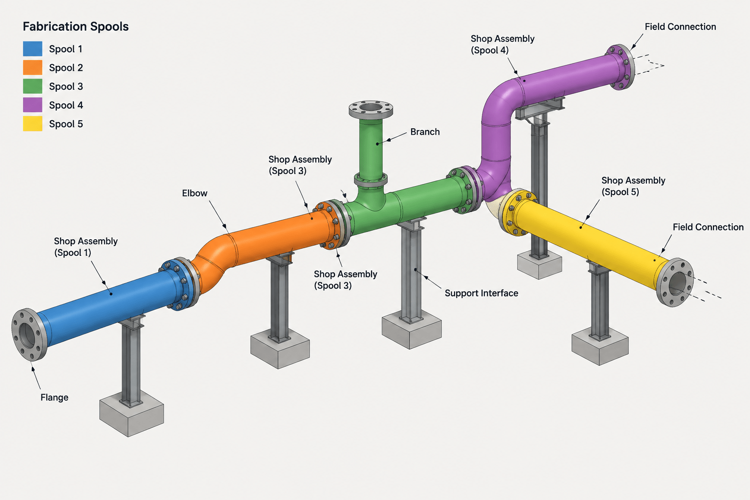
Piping spool breaks in CAD turn a continuous routed system into assemblies that can be fabricated, handled, delivered, and connected at the site. Their placement affects more than drawing organization: it influences weld classification, material ownership, installation access, interface control, and coordination between shop and field activities.
This guide explains how to evaluate proposed spool boundaries without confusing them with match lines, model divisions, or other drafting breaks. It also provides a practical framework for reviewing each boundary against fabrication sequence, transport envelope, field access, support conditions, equipment data, and downstream documentation.
A piping isometric can describe a continuous route, but the fabricator and installer rarely handle that route as one continuous assembly. It must be divided into practical pipe spools that can be fabricated, inspected, transported, lifted, positioned, and connected in the field. The locations where one spool ends and another begins are commonly called piping spool breaks.
Spool breaking is not simply a drafting exercise. A geometrically convenient division may create an assembly that cannot pass through an opening, may place a field weld where access is poor, or may separate components that should be aligned in the shop. Good spool planning connects the CAD model with fabrication and construction realities without treating preliminary assumptions as final instructions.
What a spool break represents
A spool break defines the boundary of a fabricated piping assembly. Components within that boundary may include pipe, fittings, branches, flanges, and selected attachments. The completed spool is then delivered to the installation area and joined to adjacent piping, equipment, or another spool.
The boundary can occur at several types of connections:
- A field weld between pipe ends or fittings
- A flanged joint intended for field assembly
- A threaded, mechanical, or other detachable connection permitted by the project specification
- An equipment nozzle or vendor-package interface
- A designated tie-in to existing piping
A drawing should distinguish a true spool boundary from a drafting match line, specification break, insulation break, or model-file boundary. These features may appear near one another, but they communicate different information.
Spool breaks, shop welds, and field welds
The relationship between spool boundaries and weld ownership is central to spool planning. A weld made while assembling a spool in the fabrication shop is normally part of that spool. A weld connecting separate spools at the installation site is normally identified as a field weld.
This does not mean every field weld automatically defines the best spool break. The proposed location must also be reviewed for fit-up access, inspection access, working space, support conditions, and the installation sequence. Similarly, a flange may provide a natural physical separation, but the project must still establish which spool owns the flange, gasket, bolting, and mating component.
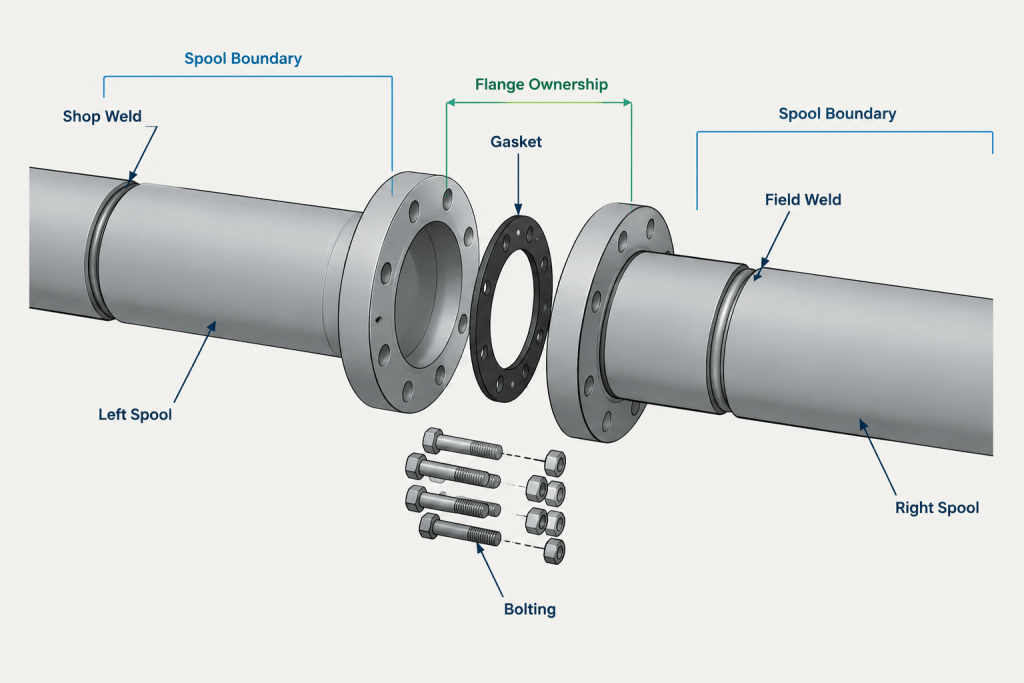
CAD geometry should support the intended weld and connection classification rather than leaving ownership to interpretation. The isometric, weld map, spool drawing, and bill of materials should all describe the same boundary.
Factors that influence spool-break locations
Fabrication access and sequence
Shop fabrication needs room to cut, fit, weld, inspect, and handle the assembly. A spool with tightly clustered branches or attachments may be easy to model but difficult to position during fabrication. The planned sequence should avoid trapping a joint behind another component or creating an assembly that cannot be rotated or supported during shop work.
Transport and handling
The outside envelope of a spool matters as much as its pipe length. Elbows, branches, valve operators, and support attachments can create an irregular shape that is difficult to load or secure. Project-specific transport and lifting limits should come from the responsible fabrication, logistics, and construction teams rather than from assumed CAD rules.
When those limits are not yet available, the model can show a proposed spool arrangement, but it should be marked as preliminary. Drafting assumptions should not be converted into undocumented fabrication requirements.
Installation path
A spool must reach its final location. Review whether the assembly can pass through structural framing, equipment areas, wall penetrations, pipe-rack bays, or congested operating spaces. The final orientation may require rotation or translation that is not obvious from a static plan view.
A useful CAD review traces the entire installation path, not just the final coordinates. Temporary obstructions and the order in which neighboring piping is installed can change what is practical.
Field-joint access
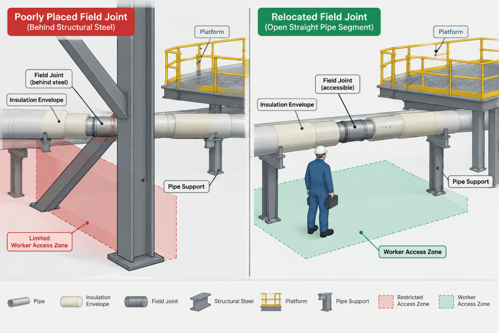
A field connection needs adequate access for alignment, welding or bolting, inspection, and any required surface treatment. Avoid placing field joints directly against structures, behind equipment, inside inaccessible penetrations, or where adjacent lines block the work area.
Access should be reviewed using the full component envelope, including insulation, attachments, valve operators, and nearby supports. A clear pipe centerline does not prove that the joint can be assembled.
Supports and stability
The temporary condition during installation may differ from the completed support arrangement. A spool can be unstable before neighboring pieces are connected or permanent supports are engaged. Spool planning should therefore be coordinated with the support layout and erection sequence.
The CAD team should identify the relationship between spool boundaries and supports but should not invent lifting points, temporary supports, or rigging instructions. Those items require review by the responsible disciplines.
Equipment and vendor interfaces
Connections at pumps, vessels, packaged equipment, and other vendor items require controlled interface information. A spool should not be finalized around an assumed nozzle location or placeholder face-to-face dimension. Vendor data status, nozzle coordinates, flange facing, orientation, and connection ownership must be clear.
Where adjustment may be needed, the project team may intentionally retain a field-fit piece or later-defined connection. That intent should be documented explicitly rather than hidden in extra model length.
Common spool-breaking strategies
| Strategy | Potential benefit | Review concern |
|---|---|---|
| Break at a flange | Provides a detachable field connection and a clear physical boundary | Confirm flange ownership, gasket and bolting responsibility, alignment, and assembly access |
| Break at a straight pipe segment | Can provide a practical field-weld location and simplify spool geometry | Verify weld access, field-fit intent, inspection access, and cut-length control |
| Keep branches within one spool | Allows branch orientation and fit-up to be controlled in the shop | Check the resulting transport envelope and fabrication access |
| Separate around a heavy or operated component | May simplify handling or allow independent installation | Review support, component orientation, joint loads, and maintenance needs |
| Break at an equipment interface | Creates a clear boundary between piping and equipment | Do not finalize against unverified vendor geometry |
| Use a designated field-fit connection | Allows controlled adjustment for actual site conditions | Define ownership, measurement workflow, and final documentation requirements |
No single strategy applies to every route. The best arrangement often combines several approaches and changes as vendor information, structural access, and construction planning become more mature.
A practical CAD workflow
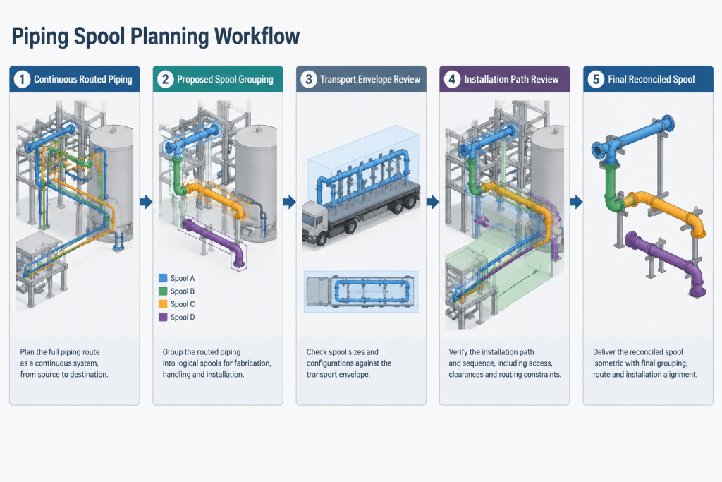
Start with an unbroken design route
First confirm connectivity, component selection, line identification, elevations, slope where applicable, and interface locations. Premature spool breaking can hide routing problems by dividing them into smaller drawings.
Identify fixed and uncertain interfaces
Mark equipment nozzles, tie-ins, penetrations, support zones, specification changes, and vendor boundaries. Separate verified geometry from placeholders. An uncertain interface is a coordination issue, not automatically a spool break.
Propose fabrication assemblies
Group pipe and components into logical shop assemblies. Consider branch clocking, flange orientation, component handling, access for fabrication, and the outside envelope. Keep the proposal editable until fabrication and construction reviewers provide input.
Review field connections in context
Inspect each proposed field joint in the model and on the isometric. Check nearby steel, platforms, cable tray, equipment, supports, insulation envelopes, and other piping. Review how workers and tools would reach the connection and how the spool would approach its installed position.
Assign consistent identifiers
Use the project naming convention for spool numbers, weld identifiers, and field-joint labels. A component should not appear in multiple spool bills of material unless the documentation method intentionally handles shared or loose items.
Reconcile deliverables
After spool boundaries are approved, compare the model, isometric, spool drawings, weld map, and material reports. Every field connection should have a consistent location and classification. Every component should have clear ownership.
How to show spool breaks clearly
The exact graphic convention is project-specific, but a clear spool drawing or isometric generally needs:
- Distinct spool identifiers placed where they cannot be confused with line numbers
- Field-weld or field-connection symbols used consistently
- Shop and field weld classifications that agree with the weld map
- Dimensions referenced to stable component centers, faces, or established coordinates
- Field-fit notes that state the intended measurement and completion workflow
- Continuation references when adjacent spools appear on separate sheets
- Revision control when a boundary or connection classification changes
A break symbol alone is not enough if the drawing does not identify what happens at the break. The connection type, ownership, and relationship to adjacent spools must be understandable without guessing.
Frequent errors to avoid
- Treating model-file limits as fabrication limits: CAD files may be divided for performance or responsibility reasons unrelated to physical spools.
- Breaking at every flange: Some flanged joints belong within an assembly, while others are intended for field connection.
- Ignoring the installation path: A spool may fit in its final space but still be impossible to move into position as modeled.
- Placing field welds in congested areas: Geometric clearance for the pipe does not establish working access.
- Finalizing around placeholder equipment: Unverified nozzle geometry can invalidate multiple spools.
- Losing material ownership: Gaskets, bolting, loose flanges, and specialty items can be omitted or duplicated when the boundary is unclear.
- Changing breaks without downstream updates: A revised spool boundary affects drawings, weld records, material reports, fabrication status, and potentially installation planning.
Spool planning is a coordinated decision
Piping spool breaks translate a continuous design route into buildable assemblies. CAD provides the geometry and documentation framework, but fabrication, logistics, construction, inspection, equipment, and support considerations determine whether a proposed arrangement is practical.
The most reliable workflow treats spool boundaries as controlled project data. Proposed breaks are reviewed in context, field connections are clearly classified, component ownership is reconciled, and changes are carried through every affected deliverable. Reference dimension tables remain essential for accurate component geometry, while spool planning determines how those components are organized for real fabrication and assembly.
Managing spool boundaries as controlled CAD data
A spool break should be treated as an identifiable project decision rather than an incidental gap in the model. Its status may change as equipment information, structural access, fabrication input, or construction sequencing becomes clearer. The CAD workflow should therefore distinguish proposed boundaries from reviewed or released boundaries using the project’s established status and revision practices.
For each proposed break, reviewers should be able to determine what connection will be completed in the field, which adjacent spool owns each component, and which documents are affected. This is particularly important for loose items, mating flanges, gaskets, bolting, field-fit pieces, and components supplied under a separate package.
Questions for a spool-break review
- Does the boundary represent a real fabrication or field-assembly division rather than a drawing or model limit?
- Can the spool be fabricated and inspected in the intended sequence?
- Can its complete outside envelope be handled and moved along the planned installation path?
- Can workers reach the field connection for fit-up, joining, inspection, and required finishing?
- Are equipment, tie-in, and vendor interfaces based on controlled information?
- Are permanent and temporary stability concerns identified for coordination with the responsible disciplines?
- Do the model, isometric, spool drawing, weld information, and material records assign the boundary consistently?
Controlling changes after spool release
Moving a spool break can alter more than the geometry shown on a drawing. It may change shop and field weld classifications, component ownership, fabrication status, material allocation, inspection records, continuation references, and the planned erection sequence. A boundary revision should therefore be communicated through the same controlled change process used for other fabrication information.
CAD automation can help identify inconsistent identifiers, duplicated components, or mismatched connection classifications, but automated checks do not establish constructability. Final acceptance still requires coordinated review of the actual fabrication, logistics, installation, inspection, support, and interface conditions.
Frequently asked questions about piping spool breaks
Is every field weld a spool break?
A field weld commonly joins separate fabricated assemblies, but its suitability as a spool boundary still depends on access, fit-up, inspection, support, and installation sequence. The drawing set should use the project’s approved classification consistently.
Is every flange a natural spool boundary?
No. A flange can provide a detachable connection, but some flanged joints may remain within a fabricated assembly. The project must define connection intent and ownership of the mating parts, gasket, and bolting.
What is the difference between a spool break and a drawing match line?
A spool break defines a physical fabrication or assembly boundary. A match line only continues the drawing or model representation into another view, area, file, or sheet. They can occur near each other without serving the same purpose.
Can spool breaks be finalized before vendor information is approved?
Boundaries near vendor equipment should remain subject to coordination when nozzle geometry, orientation, facing, or connection ownership is not controlled. Preliminary assumptions should be identified rather than presented as final fabrication information.
Who should approve spool-break locations?
Approval responsibilities depend on the project workflow. Piping design, fabrication, construction, logistics, inspection, equipment, and support disciplines may all need to review conditions that affect a proposed boundary.
What documents should be checked after a spool break changes?
Review the model, isometrics, spool drawings, weld information, material reports, continuation references, and affected fabrication or installation records. Component and connection ownership should remain consistent throughout the deliverables.