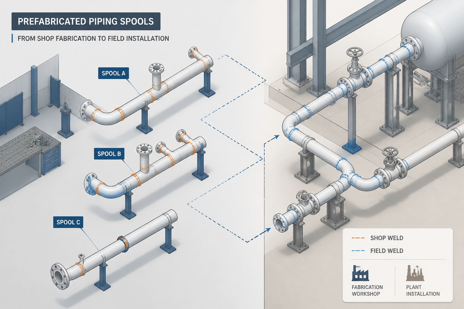
On a piping isometric, weld location is fabrication and construction information—not just a drafting annotation. The distinction between shop welds and field welds helps teams understand how a line will be divided, transported, installed, inspected, and documented.
This guide is intended for piping designers, CAD detailers, fabricators, construction planners, and reviewers. It focuses on coordination between the isometric, spool drawings, material records, weld documentation, and site installation activities. Always apply the project legend, approved drafting conventions, and document-control procedures when interpreting or assigning weld indications.
Shop welds and field welds are not merely different symbols on a piping isometric. They communicate where a joint is expected to be fabricated, how a line will be divided into transportable spools, and which connections must be completed during site installation. When this information is unclear, fabrication drawings, material takeoffs, welding records, and installation planning can quickly fall out of alignment.
A well-detailed isometric should make the intended fabrication split easy to understand without forcing the fabricator or installer to infer it from the geometry. The exact symbols, abbreviations, and approval rules depend on the project drafting standard, so the project legend and document-control requirements always take precedence. The workflow below explains the underlying coordination logic without replacing those project-specific conventions.
What is the difference between a shop weld and a field weld?
A shop weld is a weld intended to be completed in a controlled fabrication facility or workshop. It is normally associated with prefabricated pipe spools, where the fabricator can rotate the assembly, position components, perform inspection, and prepare the spool for shipment.
A field weld is a weld intended to be completed at the construction site. It may connect two delivered spools, join a spool to installed equipment or piping, or close a connection where final site measurements are needed. Field welds are often used where transport, access, existing conditions, or installation sequencing make complete shop fabrication impractical.
The distinction is about the planned location and installation sequence—not about the type of welding process, the pipe material, or whether the joint is technically capable of being welded in either location.
Why the distinction matters in CAD documentation
Shop and field weld information affects several connected documents. A change made in the isometric can alter the spool drawing, weld map, bill of materials, inspection records, and erection plan. It can also change how much pipe is shipped as one assembly and where installers need access for fit-up and welding.
- Spool definition: Weld boundaries help establish which fittings, valves, flanges, and pipe segments belong to each fabricated assembly.
- Material control: Components assigned to a spool must agree with the isometric and the fabrication material list.
- Installation planning: Field welds identify locations where site crews must align, fit, weld, inspect, and possibly test a connection.
- Inspection tracking: Weld identification must remain consistent with weld maps, examination records, and turnover documentation.
- Transport and handling: A spool split may be needed because of route access, lifting constraints, site congestion, or installation sequence.
How to show shop and field welds on an isometric
Begin with the project’s drawing legend. Do not assume that a familiar weld symbol has the same meaning in every company or CAD template. Some projects use a dedicated field-weld symbol, while others combine a weld symbol with a label, note, or weld identification convention.
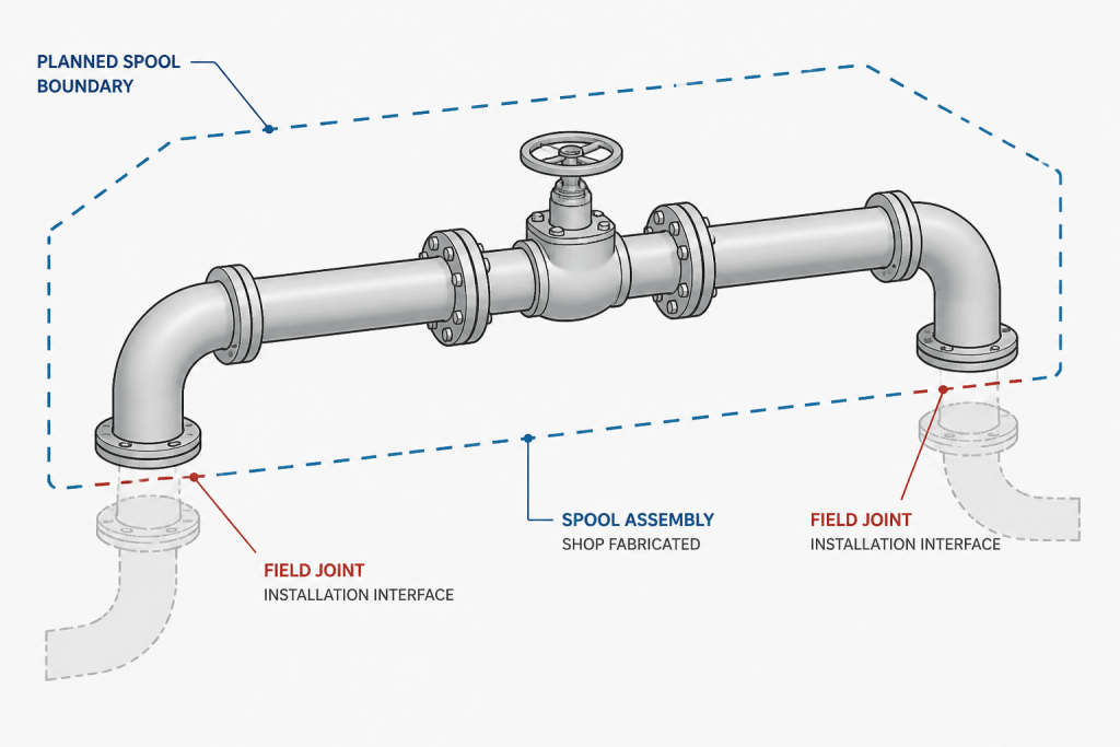
For each weld location, the drawing should answer three questions:
- Where is the joint physically located?
- Is it planned for shop fabrication or field installation?
- How is the joint identified in related records?
Place the weld indication at the actual joint location, not at a nearby open area merely because it is easier to annotate. If a leader is necessary, make its attachment point unambiguous. Avoid placing a note where it can be mistaken for a valve tag, branch designation, dimension, or component description.
When the drawing contains many welds, use a consistent identification system. The identifier may be tied to the spool, line, fabrication sequence, or project weld register. The important drafting principle is that the same identifier should not change between the isometric, spool drawing, weld map, and inspection documentation.
Planning spool breaks around weld locations
A spool break is more than a convenient place to divide a drawing. It represents a planned interface between fabrication and installation. A practical break should consider component geometry, lifting and handling, shipping, access, field fit-up, and the ability to complete the remaining work without creating an unsafe or inaccessible work position.
Common planning considerations include:
- Keep complex fitting arrangements together when shop fabrication improves dimensional control.
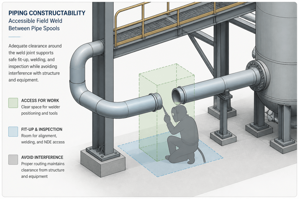
- Place field joints where installers can reach the joint and rotate or align the components as needed.
- Avoid burying a field weld behind equipment, steel, insulation, or adjacent piping.
- Consider whether valves, strainers, specialty items, and instruments need to be installed before or after the spool reaches the site.
- Coordinate the break with support locations, penetrations, existing tie-ins, and access platforms.
- Check whether the proposed spool can be transported, lifted, stored, and installed without removing attached components.
These considerations should be reviewed with fabrication and construction personnel. A geometrically valid split can still be difficult to build if the joint is inaccessible or the spool cannot be handled as modeled.
CAD workflow for assigning weld locations
1. Start with the routed centerline and components
Verify the pipe path, fittings, flanges, valves, branches, and equipment interfaces before assigning weld locations. Weld planning should follow a stable model or isometric rather than being used to compensate for unresolved routing.
2. Identify fabrication assemblies
Group the portions of the line that are intended to travel together through fabrication and delivery. Give each spool a unique, controlled identifier. Confirm that the selected boundaries do not accidentally separate a component that must be delivered as a complete assembly.
3. Mark the shop and field joints
Apply the project-approved symbols or labels at each relevant joint. Use the same graphical treatment throughout the drawing set. If a joint is provisional because final site dimensions are not available, identify that status according to the project’s established notation rather than silently treating it as a normal field weld.
4. Link the information to schedules and records
Compare the isometric against the spool list, weld register, bill of materials, and any fabrication notes. A weld that appears on the drawing but not in the weld register is a data-coordination problem, not merely a drafting issue.
5. Review constructability in three dimensions
Inspect the joint from the likely installation direction. In the model or coordinated views, check access for fit-up, welding, examination, coating, insulation, and later maintenance. A field weld that looks clear in an isometric may be obstructed in the plant arrangement.
Common documentation errors
| Error | Why it causes trouble | Better practice |
|---|---|---|
| Using an unexplained weld symbol | Fabrication and construction teams may interpret the joint differently. | Follow the drawing legend and add a clear note when the standard symbol is insufficient. |
| Changing weld IDs between documents | Inspection and turnover records become difficult to reconcile. | Use a controlled identifier shared by the isometric, spool drawing, and weld register. |
| Placing a field weld in an inaccessible area | The modeled installation sequence may not be physically achievable. | Review access, temporary supports, lifting, and adjacent systems before approval. |
| Splitting a spool through a component assembly | The delivered pieces may not match the intended fabrication scope. | Define spool boundaries deliberately and verify the material list. |
| Leaving weld status ambiguous after a revision | A routing change can invalidate the previous fabrication plan. | Recheck all affected welds, spool numbers, notes, and related records after revisions. |
Final review checklist
- Does every intended shop or field joint have a clear indication?
- Does each weld location agree with the spool boundaries?
- Are weld identifiers consistent across the drawing and related records?
- Can each planned field weld be accessed for fit-up, welding, inspection, and completion?
- Do valves, fittings, flanges, branches, and equipment connections remain assigned to the correct spool?
- Have transport, lifting, installation sequence, and site measurement needs been considered?
- Have project legends, drafting standards, and approval comments been incorporated?
The most reliable weld detailing treats the isometric as a coordination document rather than a collection of symbols. When shop welds, field welds, spool boundaries, component data, and inspection identifiers all describe the same physical assembly, the drawing becomes much more useful to fabrication, construction, quality control, and commissioning teams.
How to use this guide during a drawing review
Review shop and field weld information as part of the complete piping data set. A weld indication should agree with the physical joint, the spool boundary, the component assignment, and the records used by fabrication and quality personnel. Checking only the symbol can miss a more serious coordination problem elsewhere in the drawing package.
Review the physical interface
First confirm that the joint is located where the model and isometric show it. Then consider how the adjoining pieces will be fabricated, moved, aligned, supported, and accessed. This review connects CAD geometry with actual work in the shop and at the site.
Review the information interface
Next compare the weld indication with the spool identification, material list, weld register, inspection documentation, and revision history. Consistent identifiers make it easier to trace a joint from design intent through fabrication, installation, examination, and turnover.
Review changes carefully
Routing changes, equipment moves, support revisions, and updated site dimensions can affect more than the line shape. They may change spool boundaries, weld accessibility, component ownership, inspection planning, and installation sequence. Recheck related records whenever a revision changes the planned fabrication split.
Separate drafting clarity from engineering approval
A clearly marked weld does not by itself confirm that the location is acceptable for construction. Final decisions should be reviewed through the project engineering, fabrication, quality, safety, and construction approval processes. The isometric should communicate the approved intent without requiring users to infer missing information.
Frequently asked questions
Is a shop weld the same as a field weld with a different symbol?
No. The distinction describes where the joint is planned to be completed and how the piping assembly is divided for fabrication and installation. The project legend determines the approved graphical notation.
Can a field weld be moved after the isometric is issued?
It can be changed when the project workflow permits it, but the revision should be coordinated across the model, isometric, spool drawings, material records, weld register, inspection documents, and installation plan.
What makes a good field-weld location?
A good location is physically accessible for alignment, welding, examination, coating, insulation, and completion. It should also support the planned lifting, installation, support, and maintenance activities.
Why do spool boundaries matter when reviewing welds?
Spool boundaries identify which components are intended to travel together through fabrication and delivery. A weld location that conflicts with those boundaries can cause mismatches between the drawing, material list, delivered pieces, and site work.
Should every weld have the same identifier across project documents?
Weld identification should follow the project control system and remain traceable across the isometric, spool documentation, weld map, inspection records, and turnover information. Uncontrolled changes make reconciliation difficult.