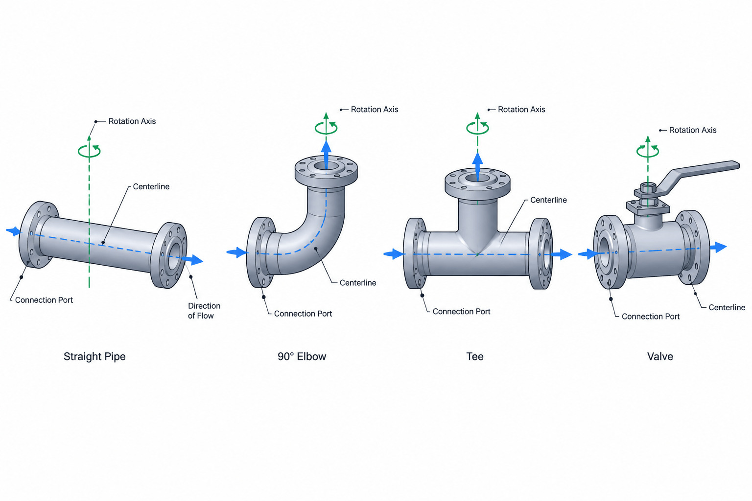
Piping component insertion points control more than initial placement. Together with connection ports, local axes, and replacement anchors, they determine whether a CAD component connects, rotates, and updates predictably throughout the model lifecycle.
This guide explains how to organize those references without confusing visual geometry with connection intelligence. Use it alongside the site’s authoritative dimensional data: the dimensions define the component, while the insertion model defines how the CAD system positions and manages it.
A piping component can have accurate dimensions and still behave poorly in CAD. The usual cause is not the component body but its insertion logic: the origin is inconvenient, connection ports are inconsistent, or the component rotates around an unexpected point. These problems become especially visible when designers replace fittings, change pipe schedules, swap valve types, or generate isometrics from a model.
Reliable piping component insertion points make catalog geometry predictable. They help components snap to pipe centerlines, preserve connected routes during replacement, and support consistent extraction of coordinates and bills of material. Dimensional reference tables remain the authority for component geometry; insertion rules determine how that geometry is positioned and connected inside the CAD system.
Origin, insertion point, and connection port are not the same thing
These terms are sometimes used interchangeably, but they serve different purposes.
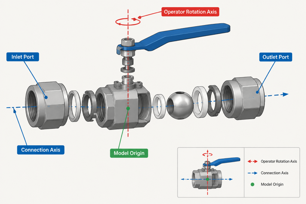
- Model origin: The local coordinate reference from which the component geometry is constructed.
- Insertion point: The point used to place a block, symbol, or component into a drawing or model.
- Connection port: A defined interface where pipe, fittings, flanges, valves, or equipment connections join.
- Rotation axis: The axis about which the component is oriented or clocked.
- Reference point: A point retained for dimensioning, reporting, or alignment even when it is not a physical connection.
A simple drafting block may use one point for several of these functions. An intelligent piping object usually should not. A valve, for example, may have two inline ports, an operator rotation axis, and a reporting origin at its center. Treating all of them as one insertion point can make orientation and replacement unreliable.
Why insertion-point consistency matters
CAD users rarely place every component once and leave it unchanged. Components are moved, mirrored, rotated, substituted, resized, and regenerated as design information develops. A sound insertion scheme lets these changes occur without rebuilding the surrounding route.
Consistent definitions improve several common workflows:
- Snapping fittings onto established pipe centerlines
- Replacing a component while preserving one or more connected ends
- Changing catalog records without shifting the entire line
- Rotating branches and valve operators predictably
- Generating reliable end coordinates and centerline dimensions
- Comparing modeled geometry with authoritative dimension tables
- Detecting disconnected or overlapping components during model QA
In contrast, an origin placed at an arbitrary corner of the component envelope may be convenient for creating a block but poor for piping design. The user must calculate offsets during placement, and later replacement may introduce unexplained movement.
Choose the origin from component behavior
There is no single best origin for every piping component. The useful question is: which geometric feature must remain stable when the component is placed, rotated, or replaced?
Inline components
Valves, reducers, couplings, and other inline components generally need ports on a common connection axis. A central origin can make rotation and visualization intuitive, while end ports define the actual connection locations. If replacement is normally anchored from one end, the software also needs a clear rule identifying the fixed port.
Do not assume the geometric midpoint is always the functional center. Components may be asymmetric, and their face-to-face or end-to-end geometry may change by type. Build the body from verified local dimensions, then define ports at the true connection interfaces.
Elbows and other direction-changing fittings
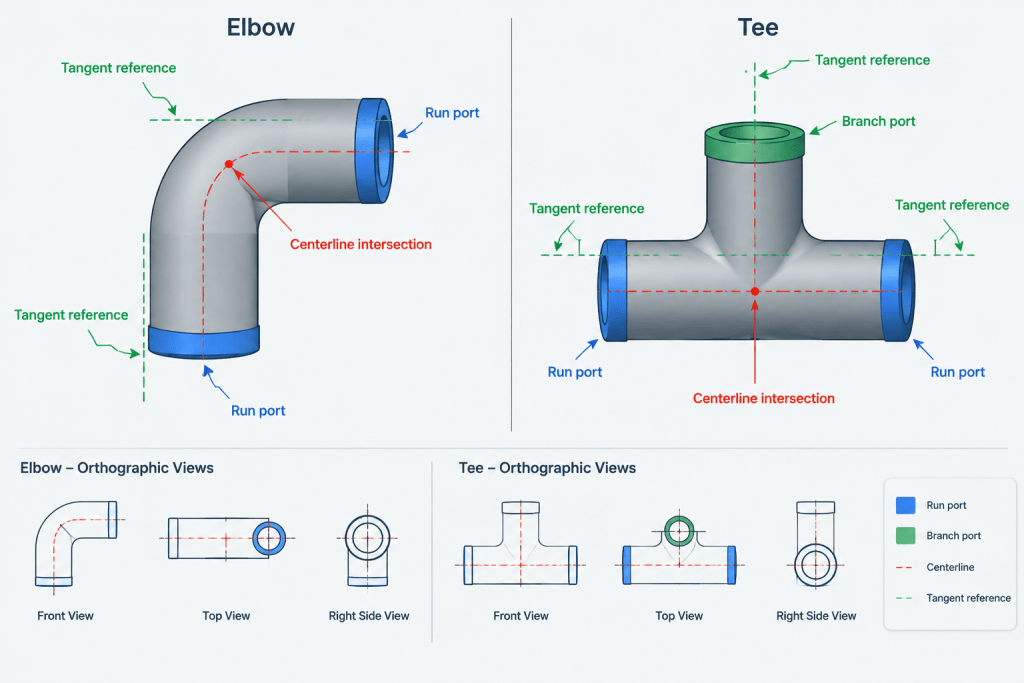
For an elbow, the intersection of the inlet and outlet centerline tangents is a useful construction reference. The actual ports remain at the fitting ends. Separating the construction reference from the connection points allows the elbow to be placed by route geometry while still reporting correct end locations.
This distinction is especially important when a CAD system trims straight pipe to fitting ports. If the ports are accidentally placed at the centerline intersection rather than the physical ends, cut lengths and graphical connections will be wrong even though the fitting appears to occupy the correct corner.
Tees and branch fittings
A tee typically has two run ports and a branch port. The run centerline and branch centerline intersection provides a logical routing reference, but each connection must retain a unique identity. Port names should indicate topology rather than depend only on the order in which geometry was drawn.
Stable port identity helps the software distinguish the continuing run from the branch. Without it, replacing or flipping the fitting can redirect connectivity, move downstream components, or produce incorrect isometric continuation.
Flanges
A flange needs a connection axis, a mating-face location, and a rotational reference for bolt-hole orientation. The mating face is usually more useful as a connection reference than the outer edge of the flange body. The opposite interface depends on flange type and should come from the applicable verified component data.
Rotation should occur around the bore centerline. A separate clocking reference can control bolt-hole orientation without changing the location of the mating face.
Equipment nozzles
Nozzle ports should represent the piping connection interface, while equipment origins should remain tied to the equipment coordinate system. Avoid using the equipment model origin as a substitute for the nozzle port. Doing so forces piping connections to depend on body geometry that may change when vendor models are updated.
A practical port data model
Each intelligent connection port should carry enough information to support placement, validation, and extraction. The exact property names depend on the CAD platform, but the underlying concepts are broadly applicable.
| Port property | Purpose | Common QA question |
|---|---|---|
| Local position | Locates the physical connection relative to the component origin | Does it match the verified component dimension? |
| Direction vector | Defines the outward connection direction | Does connected pipe extend away from the component? |
| Connection type | Describes the interface category used for compatibility checks | Can these two ends physically and procedurally connect? |
| Nominal size | Supports size matching and catalog selection | Does the port agree with the component record? |
| End-preparation attribute | Distinguishes relevant end configurations | Is the modeled joint consistent with the specification? |
| Port identifier | Preserves topology during replacement and data exchange | Will run and branch connections remain correctly assigned? |
| Clocking reference | Controls rotational orientation where it matters | Does rotation preserve the intended connection axis? |
Connection metadata should not be used to guess missing engineering information. If a required end configuration or dimensional value is unresolved, flag the component for review rather than silently applying a generic default.
Build component geometry from ports inward
A dependable library workflow begins with functional interfaces instead of visual outlines.
- Select the verified catalog record. Confirm component type, nominal size, schedule or wall designation where applicable, end configuration, and other specification-dependent attributes.
- Establish a local coordinate system. Use a consistent primary axis and define positive directions clearly.
- Place the connection ports. Locate them from authoritative local dimensional data.
- Define stable port identities. Use functional labels for inlet, outlet, run, branch, or mating interfaces as appropriate.
- Create the component envelope. Build simplified or detailed geometry around the established ports without moving them.
- Add rotation behavior. Confirm the object rotates about the intended centerline or reference axis.
- Test replacement. Substitute related catalog items and verify that the chosen anchor remains fixed.
- Test extraction. Check coordinates, connectivity, dimensions, and material descriptions in downstream outputs.
This sequence prevents a common library error: drawing an attractive component first and adding approximate connection points afterward.
Replacement rules must be explicit
When component length changes, the CAD system must decide what stays fixed. Possible behaviors include holding the upstream port, holding the downstream port, preserving the component center, or requesting a user-selected anchor. None is universally correct.
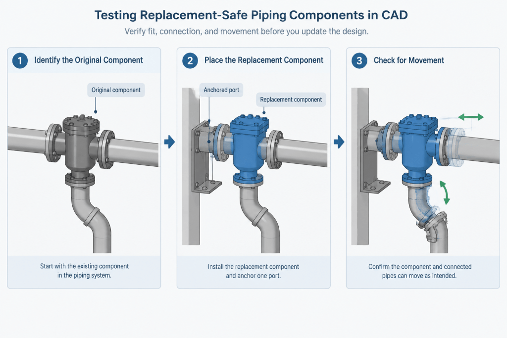
The appropriate behavior depends on design intent. A component connected directly to an equipment nozzle may need to remain fixed at that nozzle. A valve centered in a reserved access zone may need to retain its center. A fitting within a dimension-controlled spool may require deliberate review rather than automatic movement.
Record the replacement rule in library documentation and make the result visible to the user. Automatic movement that is technically consistent but unexpected can disturb supports, clearances, tie-ins, and fabrication dimensions.
Common insertion-point failures
- Origin at the bounding-box corner: Placement requires manual offsets and rotation produces wide movement.
- Ports at symbolic endpoints: Schematic graphics are mistaken for physical connection geometry.
- Inward-facing direction vectors: Connected pipe reverses or fails a connectivity check.
- Unstable port numbering: Branch and run connections swap during catalog replacement.
- Mirroring without metadata correction: Geometry looks right, but port directions or handed attributes remain wrong.
- Using one generic component for unlike end types: Visual similarity hides different connection behavior.
- Changing body geometry without retesting ports: A catalog update shifts the model while connection metadata remains at old locations.
CAD library QA checklist
Before releasing a component family, test it in a short connected route rather than viewing it only as an isolated object.
- Confirm every port lands on the intended pipe centerline.
- Compare port-to-port geometry with the site’s authoritative reference data.
- Rotate the component through multiple orientations and inspect its axis behavior.
- Connect pipe to every available port and verify outward directions.
- Replace the component with related types and sizes while observing the anchor behavior.
- Check that branches remain branches and run ports remain on the run.
- Generate a drawing or isometric and inspect dimensions, coordinates, and connectivity.
- Confirm that simplified and detailed representations use the same functional ports.
- Verify that mirrored or flipped instances retain valid metadata.
Keep geometry and connection intelligence separate
A robust piping library separates appearance from behavior. The displayed solid, double-line outline, or schematic symbol may change with drawing scale and level of detail. Connection ports, local axes, and component identity should remain stable.
This separation also makes dimensional database updates safer. Revised or corrected body geometry can be rebuilt from verified values while preserving known port conventions. Conversely, a port correction can be tested without redesigning the visual representation.
Well-defined piping component insertion points do not replace dimension tables or engineering specifications. They translate verified data into predictable CAD behavior. When origins, ports, axes, and replacement rules are treated as controlled library data, components become easier to place, easier to change, and far less likely to introduce hidden routing or fabrication errors.
Applying these rules across a CAD library
Insertion behavior should be documented as part of each component family rather than left to individual drafters. The library record should identify the local coordinate convention, functional port identities, outward directions, rotation reference, and replacement anchor behavior. This gives catalog authors, modelers, and reviewers a common basis for evaluating the object.
Check behavior in local and model coordinates
A port may be correct relative to the component origin but become incorrect after a mirror, flip, or rotation operation. QA should therefore examine both the local definition and the transformed result in the piping model. Port positions, direction vectors, and clocking references must remain synchronized with the displayed geometry.
Define acceptance by observable results
A useful acceptance test describes what the user and downstream tools should observe. Connected pipe should meet the physical interfaces, route topology should remain intact, the selected anchor should stay fixed during replacement, and extracted coordinates should agree with the modeled ports. A component should not pass merely because its solid appears correct.
Treat catalog changes as controlled revisions
Changes to body geometry, end configuration, port metadata, or anchoring logic can affect existing model instances. Review the change in a connected route and compare the resulting placement, connectivity, and extracted information. If the revised component behaves differently, document that difference so users can decide whether existing instances require inspection.
Keep unresolved data visible
Do not conceal missing connection information behind a plausible-looking symbol or generic port. Mark incomplete records for review and prevent uncertain metadata from being treated as verified design information. This preserves the distinction between a drafting placeholder and a validated intelligent piping component.
Frequently asked questions
Should the model origin always be located at a connection port?
No. The model origin may be chosen for stable construction or rotation, while connection ports remain at the physical joining interfaces. The important requirement is that each reference has a defined purpose and maintains a consistent relationship to the verified geometry.
How should a CAD system choose which port remains fixed during replacement?
The anchor should follow the design intent and the documented library rule. It may be a connected equipment interface, a selected inline end, or a component center. If the correct anchor cannot be inferred safely, the software should request user confirmation rather than move connected geometry silently.
Why is stable port identity important for tees and branch fittings?
Stable identity allows the system to distinguish the run from the branch even when the fitting is rotated, flipped, or replaced. Port order based only on drawing sequence can change unexpectedly and redirect connectivity.
Can simplified and detailed component representations use different ports?
They should use the same functional connection definitions. Display geometry may vary by drafting style or level of detail, but changing the ports between representations can alter pipe trimming, coordinates, and connectivity.
What should be checked after mirroring a piping component?
Review port locations, outward directions, handed attributes, rotation references, and extracted connectivity. A mirrored solid can look correct even when its connection metadata still reflects the original orientation.
Do insertion rules replace dimensional reference data?
No. Verified dimensional data establishes the physical component geometry. Insertion rules describe how that geometry is located, oriented, connected, and replaced within the CAD environment.