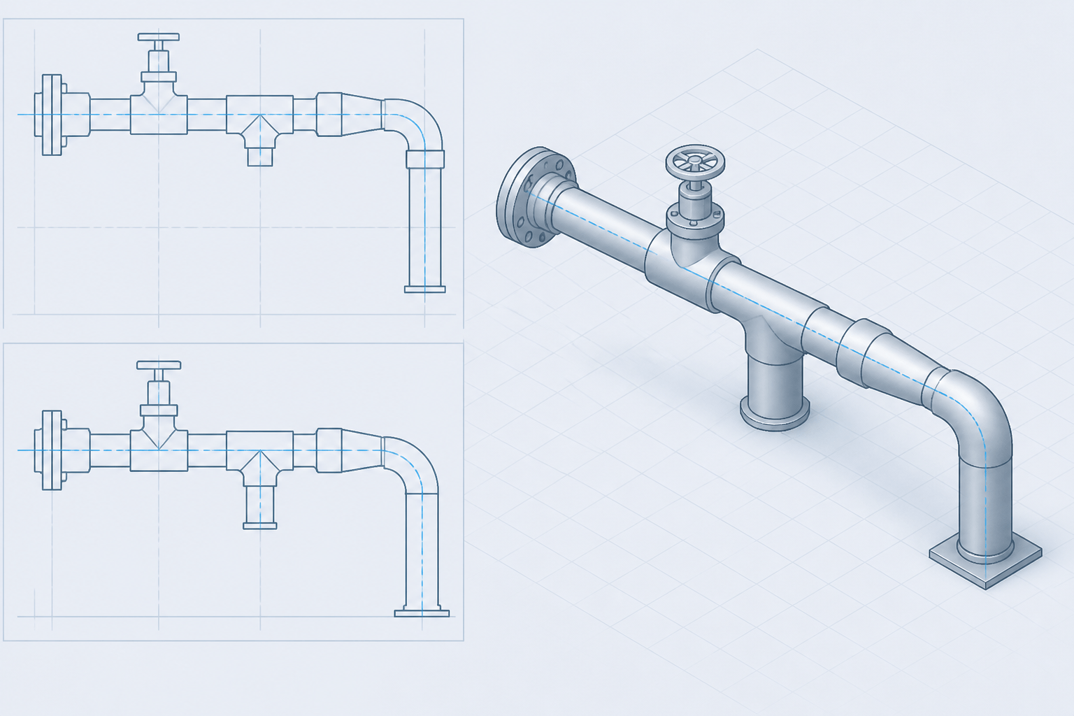
Piping CAD centerline modeling gives designers a consistent way to define where a piping route exists before reviewing its physical envelope. It connects routing geometry with fittings, equipment interfaces, dimensions, supports, and project data.
This guide explains how to use centerlines as dependable connection references, how to distinguish routing dimensions from clearance information, and how to review a model for connectivity and constructability. Use the project specification, approved component library, and verified local data for all actual component dimensions and design decisions.
Piping CAD centerline modeling is the foundation of a reliable plant layout, 3D model, and isometric drawing. The centerline represents the theoretical axis of flow through a pipe and its connected components. It is not the outside surface of the pipe, the inside bore, or the edge of insulation. Instead, it provides a consistent geometric reference for routing, connecting fittings, locating branches, and communicating elevations.
When the centerline is handled consistently, many downstream tasks become easier: fitting insertion, coordinate checking, spool creation, support coordination, insulation review, and material takeoff. When it is handled inconsistently, a model may look acceptable while containing incorrect takeouts, disconnected components, misleading dimensions, or difficult-to-fabricate geometry.
What the piping centerline represents
For a straight pipe segment, the centerline is the path between the pipe ends. For an elbow, it follows the bend path through the fitting. For a tee, valve, reducer, flange, or other component, it provides the connection axes and the points where adjoining items meet.
This representation allows different components to connect even though their physical shapes vary. A valve may have a large body, a flange may extend beyond the pipe wall, and an elbow may have a curved outer profile. The routing logic still depends on the connection centerlines and their associated ports.
- Pipe: a linear centerline between two connection points.
- Elbow: a change in direction around a defined bend path.
- Tee or branch fitting: a main run with a branch centerline intersecting it.
- Reducer: a transition between different nominal connection sizes along a common axis or offset axis.
- Valve or inline component: a component whose connection axes establish its position in the line.
- Flange: a connection plane and centerline that must align with the mating component.
The centerline is therefore a design reference, not a complete physical representation. The model still needs component geometry, connection data, material information, and clear documentation.
Why centerline modeling matters in piping CAD
It preserves connectivity
A connected line should form a continuous route from one component port to the next. Centerline-based modeling makes this continuity visible and computable. If two objects appear to touch but their connection points do not coincide, the line may be visually convincing but technically disconnected.
Connectivity affects more than the appearance of a drawing. It can influence automated isometric generation, bill-of-material extraction, flow-path review, spool segmentation, and clash checking. A small gap, incorrect axis, or accidental overlap can create errors that are difficult to find after the model has been distributed across drawings and reports.
It separates routing from physical thickness
Routing is normally established by the pipe axis. Wall thickness, outside diameter, insulation, fireproofing, and clearance envelopes are applied around that route. This separation prevents the designer from using the visible outside surface as the primary alignment reference.
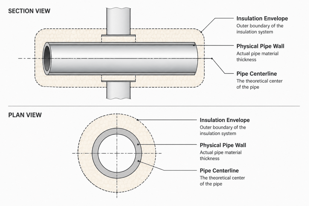
For example, a clearance dimension may refer to the outside of insulation while a location dimension refers to the pipe centerline. Both can be correct, but they describe different references. The drawing or model should make that distinction clear.
It supports repeatable component placement
Fittings and valves are easier to place when their ports are defined relative to a known axis. A component library can then use connection points, orientation rules, and takeout information instead of relying only on manually drawn outlines.
This is particularly important when a component is rotated, mirrored, or reused in another line. A block that looks correct in one orientation may create an incorrect connection when copied without its port data and insertion logic.
Build a route from connection points, not from visible outlines
A dependable workflow begins with known connection points. These may come from equipment nozzles, existing piping, structural interfaces, instruments, or other fixed references. Establish the required line direction and elevation, then place the pipe and fittings along the centerline.
- Identify the start and end connection points.
- Confirm the line size, specification, and component types from the project data.
- Set the primary routing direction and required elevations.
- Insert elbows, branches, reducers, valves, and flanges using their connection axes.
- Check that each adjoining port shares the intended axis, plane, and location.
- Add dimensions and coordinates from clearly defined references.
- Review physical envelopes, access space, support interfaces, and constructability after the route is connected.
This order matters. If the visible component outline is drawn first and the centerline is adjusted afterward, the result may contain distorted fittings, incorrect face locations, or an apparently aligned but actually disconnected route.
Centerline behavior at common piping components
| Component | Centerline or connection reference | Typical review concern |
|---|---|---|
| Elbow | The bend path between the two connection axes | Correct bend direction, radius selection, and tangent alignment |
| Tee | Main-run axis plus branch axis | Branch direction, intersection location, and branch size data |
| Reducer | Connection axis through the two ends | Concentric or eccentric orientation and correct end assignment |
| Valve | Port-to-port axis and component orientation | Flow direction, access space, handwheel or actuator clearance |
| Flange | Pipe axis and mating face plane | Face alignment, bolt orientation, gasket position, and axial takeout |
| Instrument connection | Small-bore branch axis from the main line or fitting | Connection location, orientation, accessibility, and support needs |
The table describes modeling references, not a substitute for project specifications or verified component data. The actual geometry and connection dimensions should come from the approved project library or authoritative local reference data.
Use centerline dimensions carefully
Centerline dimensions are useful because they are stable routing references. They can locate a line relative to a column grid, equipment center, structural member, or another pipe. However, a centerline dimension does not automatically describe the clearance available around the pipe.
Good drawings distinguish among at least three types of information:
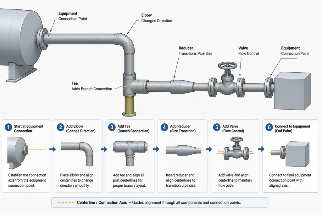
- Routing location: where the pipe axis is positioned.
- Component location: where a face, branch, valve center, or equipment connection occurs.
- Clearance or envelope: the space required around the physical component, insulation, maintenance area, or access path.
Dimensioning all three from unrelated references can create apparent conflicts. Use a consistent datum strategy and identify the reference point in the dimension note or drawing convention. Avoid dimension chains that depend on rounded graphical coordinates when a direct coordinate or verified centerline dimension is available.
Modeling centerlines in plan, elevation, and isometric views
In a plan view, a centerline primarily communicates horizontal routing. An elevation adds vertical position and slope. An isometric view communicates the three-dimensional relationship between runs, fittings, and connection points.
A line that appears continuous in plan may contain an unshown elevation change. Conversely, two lines that overlap in plan may be separated vertically. This is why centerline review should use more than one view, especially near branches, offsets, equipment connections, and congested areas.
For sloped lines, the centerline remains the routing reference while the vertical coordinate changes along the run. Show the slope using the project’s accepted drafting convention and verify that the high and low points match the intended drainage or process arrangement. Do not infer elevation from a visually exaggerated CAD view.
Common centerline modeling mistakes
- Aligning outside faces instead of connection axes: this can create incorrect joint locations.
- Ignoring fitting takeout: the route may have the right endpoints but the wrong straight-pipe lengths.
- Using a generic block without port data: visual similarity does not guarantee connectivity.
- Dimensioning insulation as if it were pipe centerline: this confuses routing with clearance.
- Failing to rotate branch components: a branch may point in the correct general direction but be clocked incorrectly.
- Overlapping components to hide gaps: graphical overlap can mask a disconnected or duplicated connection.
- Changing the route without updating metadata: line number, size, specification, and component data can become inconsistent with geometry.
A practical centerline quality check
Before issuing a model or drawing, review each route from end to end. Start at a known connection and follow the centerline through every fitting, valve, branch, and termination. At each joint, confirm the connection point, axis, size, orientation, and component identity.
Then review the route against the surrounding design. Check equipment access, structural openings, insulation space, support locations, maintenance envelopes, and nearby lines. Finally, compare the graphical route with the associated line list, piping specification, component data, and isometric output.
Centerline modeling is simple in concept but powerful in practice. Treating the centerline as the primary routing reference creates a stable link between design intent, CAD geometry, component data, and fabrication documentation. The result is not merely a cleaner drawing; it is a more traceable piping system that is easier to review and update.
How to use this guide with a piping model
Centerline modeling is most effective when geometry, component data, and drafting conventions are reviewed together. A clean-looking route is not necessarily a connected or fabrication-ready route. The model should preserve the relationship between each port, fitting axis, component face, and adjoining pipe segment.
Keep geometry and metadata synchronized
A route change can affect more than the visible pipe path. It may also change line connectivity, fitting orientation, support interfaces, insulation review, spool boundaries, and the information shown on an isometric drawing. After revising geometry, confirm that the associated line and component data still describe the modeled arrangement.
Review the model in layers
- Connectivity: confirm that adjoining ports meet at the intended location and share the required axis or connection plane.
- Routing: check direction changes, elevations, slopes, branches, and equipment interfaces.
- Physical envelope: review pipe wall representation, insulation, valves, flanges, instruments, access areas, and nearby obstructions.
- Documentation: compare dimensions, coordinates, line information, component identification, and generated drawings with the model.
Use the right reference for each review
The pipe centerline is appropriate for establishing route location and connectivity. A component face may be the correct reference for an equipment or flange interface. An outside envelope or maintenance area may be required for clearance review. Keeping these references distinct makes drawings easier to interpret and reduces the risk of treating a routing dimension as a clearance dimension.
Coordinate CAD and fabrication review
Designers should review centerline geometry before relying on downstream outputs such as isometrics, material reports, or spool information. Fabrication-oriented review should confirm takeouts, joint locations, component orientation, access requirements, and the consistency of the modeled route with approved project data. These checks support better communication, but they do not replace engineering review or project-specific verification.
Key relationship to remember
The centerline establishes the route; component geometry explains what occupies that route; dimensions communicate its location; and metadata identifies what the components represent. Reliable piping CAD depends on all of these layers agreeing with one another.
Frequently Asked Questions
What is a piping CAD centerline?
A piping CAD centerline is the theoretical axis used to define a pipe route and connect component ports. It is a geometric reference rather than the outside surface, bore, insulation boundary, or complete physical shape of the piping.
Why should fittings be placed from connection axes?
Connection axes provide a repeatable reference for fitting insertion, orientation, and connectivity. Placing components from visible outlines can create incorrect face locations, gaps, overlaps, or distorted relationships between adjoining items.
Is a centerline dimension the same as a clearance dimension?
No. A centerline dimension locates the routing axis, while a clearance dimension describes space around the physical component, insulation, access area, or maintenance envelope. Drawings should identify which reference each dimension uses.
How can a CAD model be checked for centerline connectivity?
Follow the route from a known connection through every pipe segment, fitting, branch, valve, and termination. At each joint, check the connection location, axis, orientation, component identity, and applicable size or specification data from the approved project information.
Why should piping routes be reviewed in multiple views?
Plan, elevation, and isometric views reveal different aspects of a route. A plan can hide elevation changes, while overlapping plan graphics may represent piping separated vertically. Multiple views help expose routing, branch, slope, and congestion issues.
Does centerline modeling replace physical clearance review?
No. Centerline modeling establishes the route, but physical clearance review still requires component geometry, insulation information, access envelopes, support interfaces, and surrounding layout context.