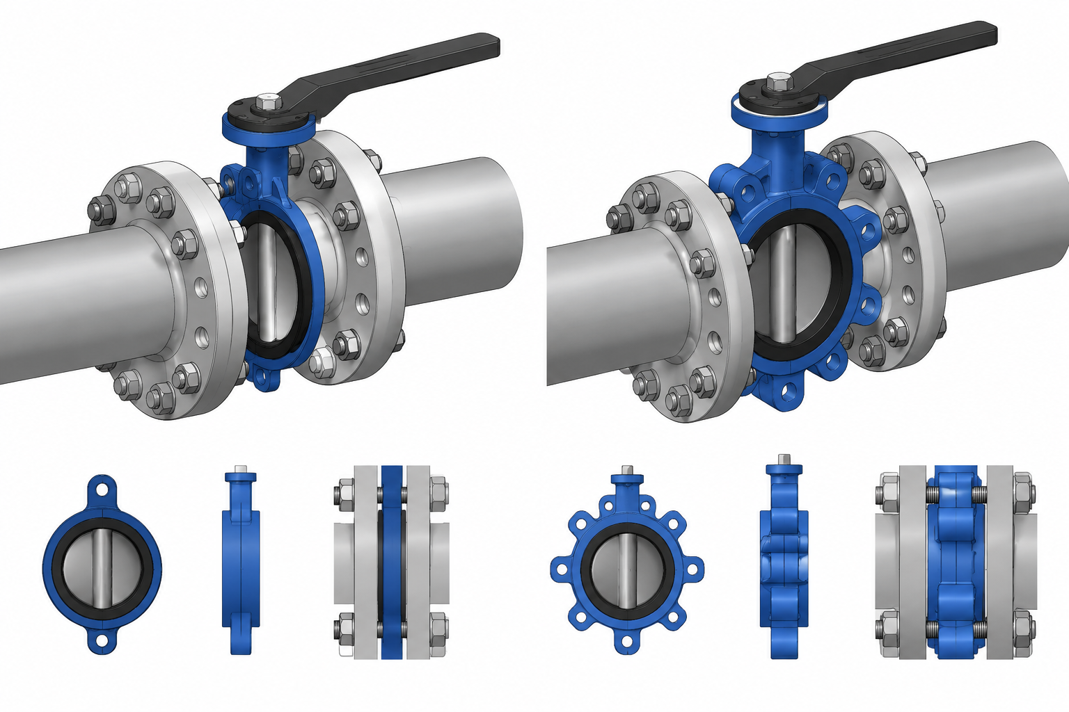
Choosing between wafer and lug butterfly valves is not simply a matter of selecting a similar-looking CAD component. The body interface determines how the adjoining flanges are fastened, while the selected valve design affects joint modeling, access checks, removal planning, and material identification.
This guide explains the practical differences between wafer and lug butterfly valves from a piping design and drafting perspective. It focuses on what the model must communicate, which details require product-specific verification, and how to avoid assumptions that can create conflicts during installation or maintenance.
Key distinction: a wafer valve is generally clamped within a flange assembly, while a lug valve connects the flanges to body lugs. That basic difference should remain visible in component data even when early CAD geometry is simplified.
Wafer and lug butterfly valves can look nearly identical in a piping plan or simplified 3D model. Both commonly place a compact valve body between mating pipe flanges, and both use a rotating disc to control flow. Their flange interfaces, bolting arrangements, installation behavior, and maintenance implications are not necessarily the same.
For a piping designer, the distinction affects more than the valve symbol. It can influence bolt selection, flange spacing, accessibility, component replacement, piping support, and the information carried into an isometric or bill of materials. The correct configuration must come from the piping specification, valve data sheet, approved manufacturer information, and applicable project requirements—not from appearance alone.
What Is a Wafer Butterfly Valve?
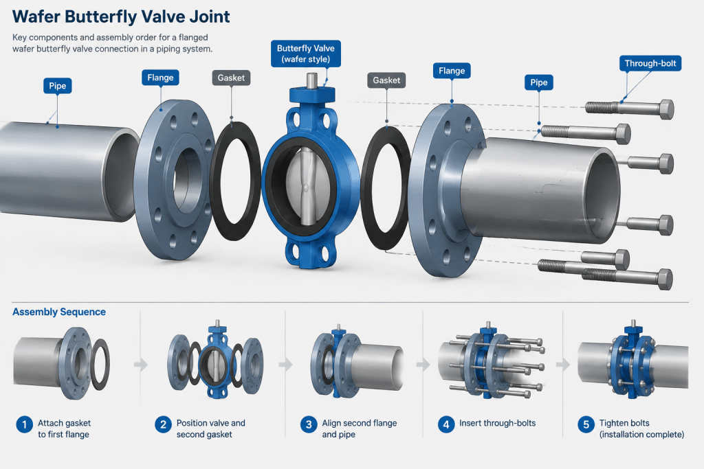
A wafer butterfly valve has a compact body intended to be clamped between two pipe flanges. The flange bolts or studs generally pass from one mating flange to the other around the valve body. The valve may include locating features or partial body holes that help center it, but the adjoining flanges and through-bolting form the principal joint assembly.
In CAD, a wafer valve should not be treated as an independent flanged component with conventional flange ends. Its body sits inside a joint stack that includes both mating flanges, the valve, required sealing elements, and the associated bolting arrangement.
Key drafting implications include:
- The valve body must be centered correctly between the flange faces.
- The model must represent the verified installed face-to-face dimension.
- Bolt paths must be checked for interference with the body, operator, neck, and nearby steel.
- The surrounding piping may need to move or spread sufficiently for valve removal.
- The bill of materials must distinguish the wafer body from a valve supplied with integral flanged ends.
What Is a Lug Butterfly Valve?
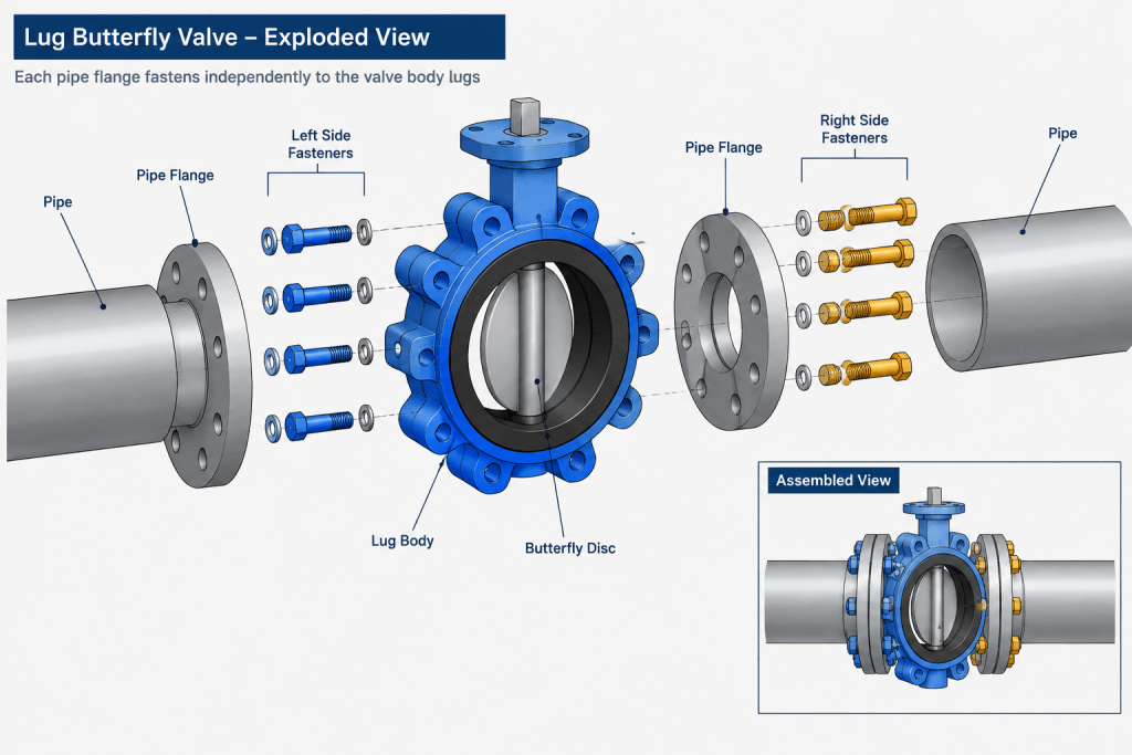
A lug butterfly valve has projecting lugs distributed around the body. Fasteners connect each pipe flange to the valve body rather than necessarily extending through the entire flange-to-flange assembly. Depending on the valve design, the lugs may be threaded or may use another manufacturer-defined bolting arrangement.
This configuration can provide assembly and maintenance options that differ from those of a wafer valve. However, designers should not assume that every lug valve permits removal of downstream piping, dead-end service, or pressure retention with piping disconnected on one side. Those capabilities depend on the particular valve construction, rating, bolting, seat design, service conditions, and manufacturer limitations.
In a CAD model, the lug pattern may be simplified at early design stages, but the connection type should remain identifiable in component data. Detailed models used for constructability or bolt-clearance review should show enough body and lug geometry to detect relevant conflicts.
Wafer and Lug Valve Comparison
| Design issue | Wafer valve | Lug valve |
|---|---|---|
| Basic body interface | Clamped between mating flanges | Flanges fasten to body lugs |
| Typical fastener concept | Through-bolting or studs spanning the joint | Separate fasteners associated with each flange side |
| CAD identification | Compact body without a full integral flange | Compact body with visible or data-defined lugs |
| Removal planning | Usually requires evaluation of flange separation and through-bolt withdrawal | Requires evaluation of side-specific fasteners, flange movement, and actual valve capability |
| One-sided service assumption | Do not assume | Do not assume; verify the exact product and project requirements |
| Required dimensional source | Approved valve data and applicable dimensional reference | Approved valve data and applicable dimensional reference |
This comparison describes configuration concepts, not universal performance rules. Valve suitability can also depend on body material, seat and liner materials, disc construction, shaft design, actuation, pressure-temperature limits, fluid characteristics, and piping specification requirements.
Model the Installed Stack, Not Just the Valve Body
The space between pipe flange faces must match the verified installed dimension for the selected valve. Avoid measuring a generic CAD block and treating that measurement as procurement data. Similar-looking butterfly valves can have different body envelopes, neck heights, operators, liners, sealing arrangements, or dimensional references.
A useful modeling sequence is:
- Establish the pipeline centerline and flange-face locations.
- Insert the valve using a defined center or flange-face reference.
- Apply the approved face-to-face or installed-width dimension.
- Confirm whether separate gaskets are required, prohibited, or incorporated into the valve design.
- Add the correct flange and fastener concept.
- Check disc movement, operator access, and removal space.
Do not automatically add conventional flange gaskets to every butterfly valve assembly. Some resilient-seated designs use body-mounted sealing surfaces or liners that interact directly with the mating flanges. Other designs may have different gasket requirements. The valve documentation and piping specification should control the modeled joint stack.
Check the Butterfly Disc Envelope
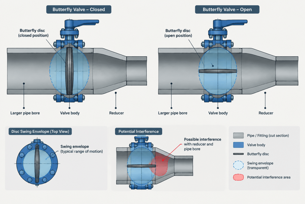
The disc rotates within the valve body and may extend beyond the body faces while opening. That moving envelope can conflict with adjacent pipe bores, flange geometry, liners, reducers, check-valve internals, or other closely coupled components.
A simplified valve symbol rarely communicates this risk. For layout and review, include a disc-swing envelope or retain an accessible reference layer showing the open and closed positions. The envelope does not need manufacturing-level detail, but it should be based on verified product geometry when clearance is critical.
Particular attention is warranted when a butterfly valve is installed next to:
- A reducer or other bore transition
- A lined pipe or lined fitting
- A check valve with internal moving parts
- A flow meter or instrument requiring a specific installation arrangement
- A nozzle with an unusual internal profile
- A thick flange, spacer, or specialty joint component
Bolting and Tool Access
Bolting should be reviewed as an assembly operation rather than represented only as a note. A through-bolt used with a wafer valve needs a practical insertion and withdrawal path. A lug valve requires access to fasteners on both sides, including room for tightening tools.
Potential conflicts include the gearbox, hand lever, actuator bracket, valve neck, pipe support steel, equipment casing, floor edges, and nearby parallel lines. Even if the fasteners fit in the final position, the joint may still be difficult to assemble if a bolt cannot be inserted or a tool cannot reach the nut or bolt head.
At the drawing stage, show or verify:
- Which side receives the bolt head, nut, or stud hardware
- Whether fasteners can be inserted without removing unrelated equipment
- Whether the body shape obstructs a straight tool approach
- Whether flange-hole orientation matches the intended assembly
- Whether insulation will conceal or restrict the fasteners
Operator Orientation Is a Separate Decision
The valve body connection and the operator orientation should be controlled as separate pieces of data. Rotating a valve operator to clear an obstruction may affect access, position indication, actuator supports, cable routing, pneumatic tubing, drainage, or the ability to remove the operator.
A lever-operated valve needs room for its complete operating arc. A gearbox requires handwheel access and removal clearance. An actuated valve may require additional envelope information for the actuator, mounting hardware, local accessories, and connection points. Avoid using a generic operator envelope after the actual valve package has been selected.
Plan for Removal and Flange Separation
A butterfly valve can be compact in service but awkward to remove. The design review should ask how the valve will be released from the flanges, how much axial movement is available, where the removed valve will travel, and whether the operator must be detached first.
For wafer valves, through-bolting and the need to separate mating flanges are central concerns. For lug valves, separate side bolting may change the sequence, but it does not eliminate the need to evaluate pipe movement, sealing surfaces, valve weight, or service isolation.
Adjacent anchors, rigid equipment nozzles, short spool pieces, and tightly supported pipe can prevent useful flange separation. A removable spool or another approved dismantling strategy may be needed where maintenance access is important. The CAD model should communicate the intended removal route instead of assuming that nominal clearance around the installed body is sufficient.
Information to Carry into Drawings and the BOM
The component record should contain enough information to prevent a wafer valve from being replaced accidentally with a lug or flanged alternative. Depending on the project workflow, useful fields include:
- Valve tag and line number
- Valve type and connection style
- Nominal size and specified rating designation
- Body, disc, seat, and other required material identifiers
- Manual operator or actuator type
- Normal position and fail position when applicable
- Flow direction requirement, if the selected design is directional
- Approved face-to-face reference
- Manufacturer and model data when released for design
Do not infer pressure capability from the nearby flange designation alone. The complete valve assembly has its own limitations, which may depend on materials, temperature, differential pressure, seat design, and operating conditions.
Practical CAD Review Checklist
- Confirm whether the selected valve is wafer, lug, or integrally flanged.
- Use verified face-to-face and body-envelope information.
- Check whether separate gaskets belong in the assembly.
- Represent the correct through-bolt or lug-bolt concept.
- Review bolt insertion, tightening, and withdrawal paths.
- Check the rotating disc against adjacent internal geometry.
- Verify lever, gearbox, or actuator operation and access.
- Evaluate flange separation and the valve removal route.
- Confirm that supports do not prevent the planned maintenance sequence.
- Keep the model, isometric callout, valve list, and bill of materials consistent.
Final Drafting Principle
Wafer and lug butterfly valves should not be differentiated only by a small graphic change. Their connection logic affects the entire assembly: flange interfaces, bolting, sealing, disc clearance, access, and maintenance. Model enough geometry to support the current design decision, attach reliable component data, and verify product-specific details before issuing fabrication or construction documents.
Use a Clear Verification Hierarchy
When model geometry, a catalog image, and project documentation appear inconsistent, do not resolve the difference by visual judgment alone. Begin with the piping specification and valve data sheet, then confirm the selected product configuration using approved manufacturer information. The CAD representation, valve list, isometric description, and bill of materials should follow the verified selection.
A generic library component may be suitable for preliminary layout, but it should be identified as provisional. It should not silently become the dimensional or procurement basis for the installed valve.
Match Model Detail to the Design Question
Early routing work may require only the valve centerline, installed width, connection style, and an approximate operator envelope. Constructability and maintenance reviews require more information, such as body projections, lug locations, fastener access, disc movement, and the space needed to separate the joint.
Adding detail is useful only when the geometry is controlled and traceable. Decorative fasteners or lugs based on an unrelated valve can create false confidence. Where exact product geometry is unavailable, use clearly identified clearance envelopes and record the unresolved items for later review.
Coordinate the Valve with the Piping Assembly
The valve cannot be checked independently from the connected pipe, flanges, supports, insulation, operator, and nearby equipment. A connection that fits geometrically may still be impractical if fasteners cannot be inserted, tools cannot approach the joint, or rigid supports prevent flange movement.
Review the assembly from installation and maintenance viewpoints. Consider the order in which fasteners, valve body, operator, and adjoining spool pieces would be installed or removed. This sequence-based review often reveals constraints that are not apparent in a static model.
Control Substitutions During Design Development
A wafer valve, lug valve, and integrally flanged valve should not be treated as interchangeable placeholders. A substitution can change the bolting concept, body envelope, installed joint arrangement, operator position, removal sequence, and bill-of-material requirements.
If the selected connection style changes, repeat the interface review rather than updating only the component description. Confirm flange compatibility, joint sealing, fastener access, disc clearance, support interaction, and maintenance space using the newly approved valve information.
Recommended CAD Handoff Information
- Identify the connection style as wafer, lug, or integrally flanged.
- State whether the geometry is preliminary, vendor-based, or approved for the current design stage.
- Keep the installed-width reference traceable to its controlled source.
- Record unresolved gasket, fastener, operator, and directional requirements.
- Flag clearance envelopes that must be updated after product selection.
- Keep component attributes consistent across the model, drawings, valve list, and bill of materials.
Frequently Asked Questions
Can a wafer butterfly valve and a lug butterfly valve use the same CAD symbol?
A simplified schematic symbol may not show every body feature, but the connection style should remain identifiable in the component data and associated documents. Layout and fabrication models should include enough distinction to support bolting, clearance, and maintenance reviews.
Does a lug butterfly valve always allow piping to be disconnected on one side?
No. That capability must be verified for the exact valve construction, service conditions, bolting arrangement, and manufacturer limitations. The presence of body lugs alone does not establish suitability for one-sided or dead-end service.
Should standard flange gaskets always be modeled beside a butterfly valve?
No. Sealing arrangements vary by valve design. Some valves use liners or body-mounted sealing surfaces, while others require a different joint arrangement. Follow the valve documentation and piping specification rather than applying a generic gasket rule.
Why should the disc envelope appear in a CAD review?
The rotating disc may project into adjoining components as the valve opens. A verified movement envelope helps identify possible conflicts with pipe bores, liners, reducers, internal valve parts, and other nearby geometry.
Is visible clearance around the installed valve enough for maintenance?
Not necessarily. Maintenance also requires a workable fastener-removal path, flange movement, tool access, handling space, and a route for removing the body or operator. These needs should be reviewed as an assembly sequence.
Can a generic valve model be used for final design?
A generic model can support preliminary routing if its status and limitations are clear. Final interface, fabrication, and construction decisions should use verified information for the selected valve and its complete installed assembly.