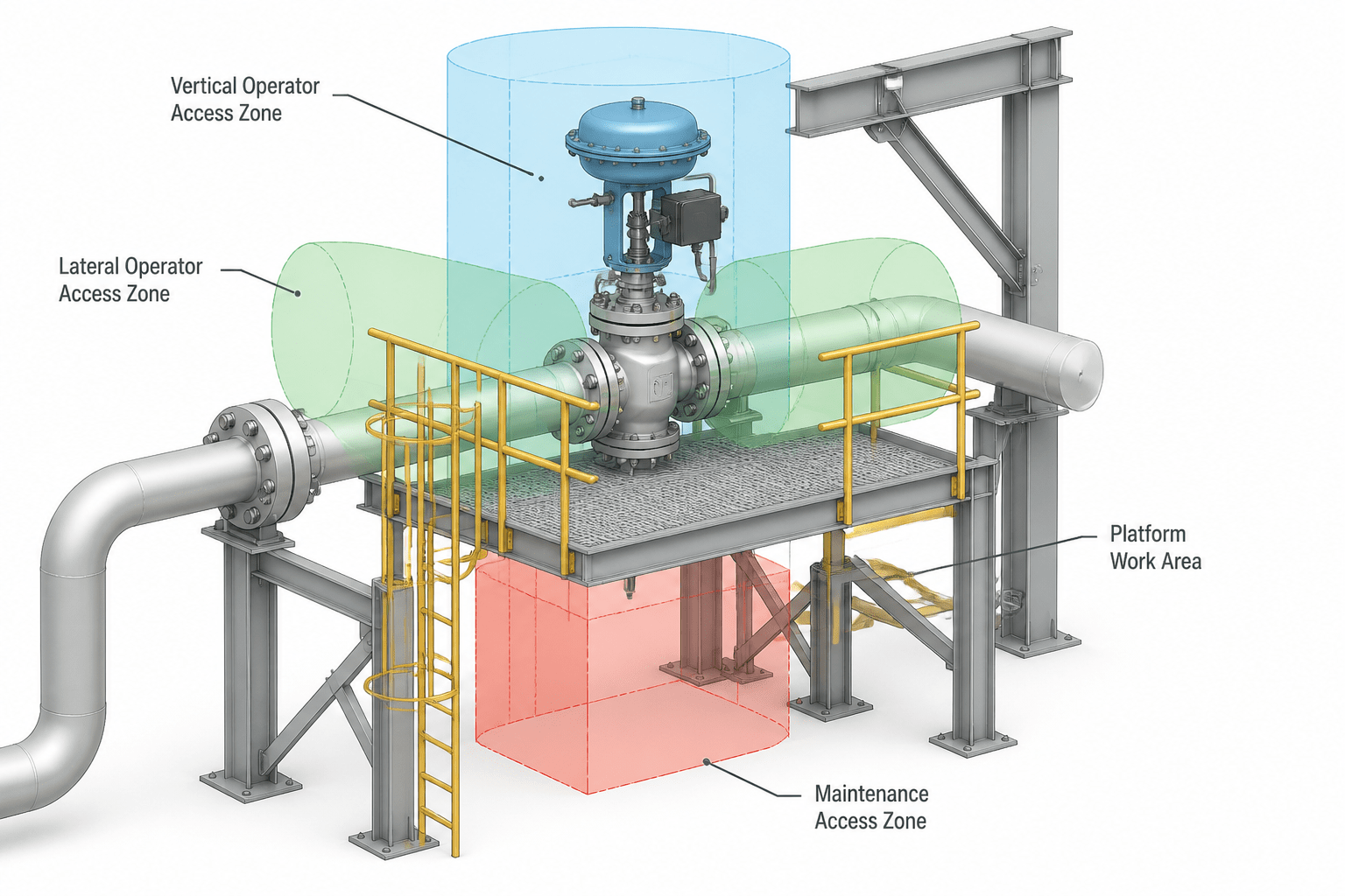
Valve placement in a piping model is only the beginning of an effective layout review. A symbol may confirm connectivity while concealing an actuator conflict, an unreachable handwheel, or a blocked path for removing the valve.
This guide explains how to communicate operating access and maintenance requirements in piping CAD. It is intended for designers, drafters, model reviewers, and project coordinators who need valve arrangements to remain understandable through design, construction, and maintenance reviews.
Valve location is not fully resolved when the pipe centerline, fitting, and valve symbol appear in the model. A routed valve may still be difficult to operate, impossible to remove, or blocked by nearby steel, equipment, insulation, or another line. Good piping CAD documentation therefore needs to communicate more than flow direction and nominal connectivity. It must also show how people will reach the valve and how the component can be maintained.
This guide explains a practical workflow for representing valve access and maintenance clearances in piping drawings and 3D models. It complements valve orientation, support, insulation, and general arrangement reviews without replacing the project’s design criteria, vendor information, or applicable engineering requirements.
Access clearance and maintenance clearance are different
Access clearance is the space needed to reach and operate a valve during normal use. The required space depends on the operator type, operating position, handwheel or lever movement, chain wheel arrangement, and whether the valve is operated from a platform, floor, ladder, or other access point.
Maintenance clearance is the space needed to inspect, remove, repair, or replace the valve and its related parts. This may include room for bolting, bonnet removal, actuator withdrawal, packing adjustment, gasket replacement, or lifting equipment.
These spaces can overlap, but they should not be treated as the same envelope. A valve may have enough room for an operator’s hand while still lacking the withdrawal path needed to remove an actuator or bonnet.
| Review item | CAD question | Typical evidence |
|---|---|---|
| Normal operation | Can the operator reach and move the control? | Operator position, access platform, and movement envelope |
| Inspection | Can personnel see the valve, tags, joints, and indicators? | Clear sightline and readable annotation |
| Removal | Can the component leave its installed position? | Withdrawal path and removable spool or joint |
| Maintenance | Is there space for tools and replacement parts? | Working zone and access-side clearance |
| Safety review | Does the arrangement avoid creating an obstructed route or awkward operating position? | Plan, elevation, and access coordination review |
Start with the valve data, not the symbol
Before adjusting geometry, collect the information that controls the valve’s physical envelope. The piping model may contain only a simplified symbol or nominal body representation, while the actual purchased component may have a larger actuator, extended bonnet, positioner, gearbox, or accessory assembly.
- Valve type and end connection arrangement
- Operator type, including handwheel, lever, gearbox, actuator, or chain operation
- Actuator orientation and adjustment or removal direction
- Face-to-face or end-to-end information used by the piping model
- Manufacturer or supplier outline data, when available
- Insulation, cladding, heat tracing, and removable-cover requirements
- Nearby instruments, drains, vents, supports, platforms, ladders, and structural members
Keep the source of each important dimension traceable in the project data. If supplier information is not available, use the approved project library representation and mark assumptions for later verification. Do not make a generic block appear more precise than the information behind it.
Model the operating envelope separately from the valve body
A reliable CAD workflow represents the valve body and the space around it as separate types of information. The body establishes pipe connectivity and general geometry. The operating envelope shows where the handwheel, lever, actuator, or chain needs to move. The maintenance envelope shows where parts, tools, or lifting paths may be required.
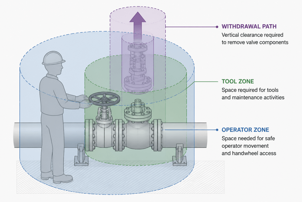
These envelopes do not always need to be modeled as permanent solid geometry. Depending on the CAD system, they may be represented with transparent solids, reference surfaces, clearance boxes, 2D overlays, or dedicated review layers. The important point is that reviewers can distinguish physical equipment from analytical space.
Useful envelope categories
- Operator envelope: space for normal movement of a handwheel, lever, chain wheel, or actuator control.
- Personnel access zone: space needed for a person to approach, stand, reach, and see the operating point.
- Removal envelope: the path followed by a bonnet, actuator, trim assembly, or valve body during removal.
- Tool and bolting zone: space for wrench movement, fastener access, and joint separation.
- Lifting or handling zone: space for a hoist, temporary lifting point, trolley, or manual handling route where the project requires one.
Use clear layer names, colors, or object properties for these categories. A single generic “clearance” layer often hides the difference between a handwheel sweep and a full maintenance withdrawal path.
Check access in more than one view
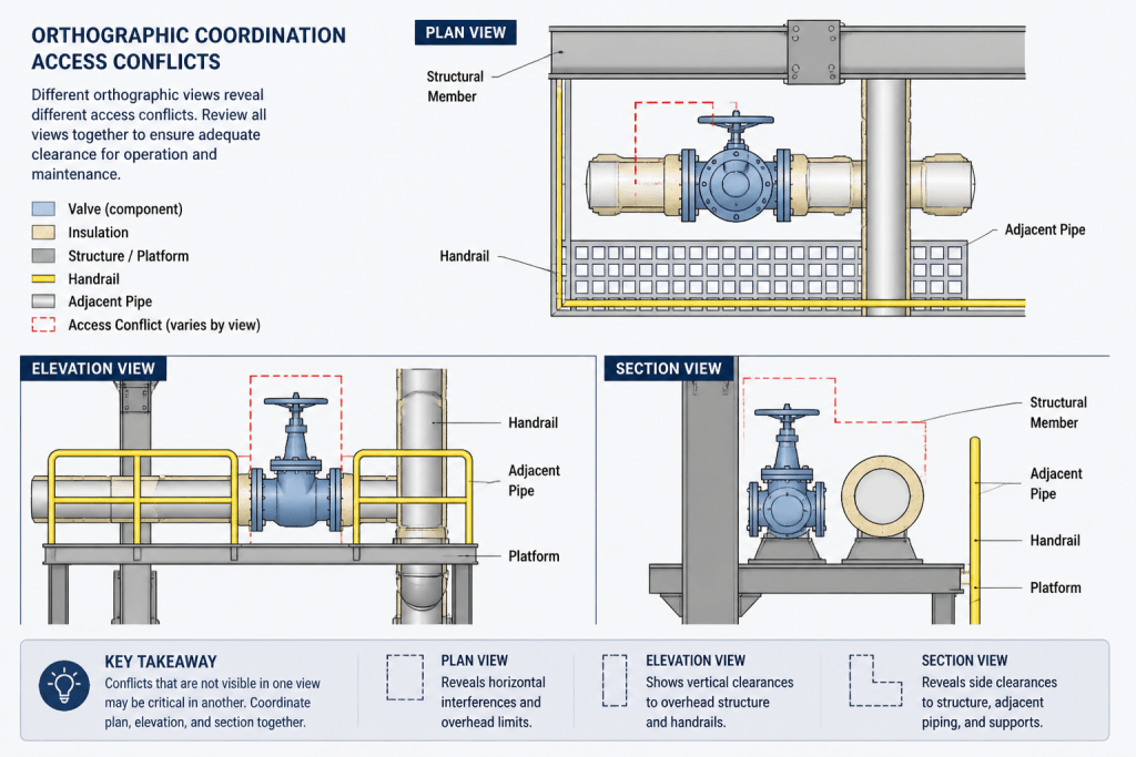
A valve can look accessible in plan while being blocked in elevation. Review each important valve in the views that describe its actual approach and removal direction.
Plan view
Use plan view to check neighboring pipe runs, columns, equipment outlines, handrails, and the horizontal swing of levers or chain wheels. Confirm that a person can approach from the intended side and that the valve is not hidden behind another component.
Elevation view
Elevation is essential for checking operating height, platform relationship, overhead obstructions, pipe racks, and vertical withdrawal paths. It also shows whether a valve operator conflicts with insulation, structural steel, or a higher-level line.
Section view
A section can clarify cramped arrangements that are ambiguous in plan and elevation. Use it to show access through a rack, around equipment, or beneath a platform. Sections are especially useful when a valve is near a wall, penetration, vessel shell, or multi-level structure.
Coordinate the valve with access structures
Valve access is a coordination issue, not only a piping issue. When a valve requires a platform, ladder, davit, monorail, or removable handrail, show the relationship in the appropriate drawing or model view. The piping layout should identify the required access point, while structural and layout disciplines confirm that the supporting arrangement can be built and used.
Pay attention to elevation transitions. A valve that is reachable from one platform may become inaccessible after insulation, grating, handrails, or adjacent equipment are added. Likewise, a valve operated from grade may need a different orientation if a future platform is introduced.
Where access depends on a removable guard, panel, or handrail, identify that dependency instead of implying permanent open space. A note or model property can help communicate whether the item is fixed, removable, or temporary for maintenance.
Show removal paths and break points clearly
Maintenance often requires more than opening a valve. A component may need to be separated from adjacent flanges, removed axially from the line, lifted vertically, or withdrawn sideways. The drawing should make the intended break point and removal direction understandable.
- Identify removable flanged joints, unions, or spool breaks where they are part of the maintenance concept.
- Show the likely withdrawal direction with a reference arrow or maintenance note.
- Check that nearby pipe, steel, equipment, insulation, and platforms do not block the path.
- Coordinate actuator removal separately when the actuator is larger or moves differently from the valve body.
- Record unresolved supplier-dependent dimensions as review items rather than hiding them in simplified geometry.
A removal envelope is not automatically a lifting plan. If a component requires special handling equipment, the project should define that requirement through the appropriate engineering and construction process.
Use a focused CAD review sequence
A repeatable review prevents access checks from becoming an informal visual judgment. For each valve or valve group, use the following sequence:
- Confirm the valve tag, line number, service context, and operator type.
- Verify that the modeled body and operator orientation match the approved data.
- Identify the normal operating side and the person’s approach path.
- Review handwheel, lever, chain, or actuator movement without nearby obstructions.
- Check visibility of the valve tag, indicator, position markings, and adjacent joints.
- Trace the removal path for the body, bonnet, actuator, and any related trim or accessory.
- Review platform, ladder, handrail, grating, structural, insulation, and equipment interfaces.
- Record the result as acceptable, conditionally acceptable, or requiring redesign under the project’s review system.
Use model viewpoints or saved camera positions for congested valve groups. A saved viewpoint allows piping, structural, mechanical, and construction reviewers to inspect the same arrangement without repeatedly recreating the view.
Common CAD mistakes to avoid
- Using the nominal valve block as the complete envelope: the actuator or bonnet may extend beyond the library symbol.
- Checking only the operator: normal operation may work even though maintenance removal is blocked.
- Ignoring insulation and cladding: the finished outside surface can change access and tool space.
- Showing an access platform without the approach path: a platform does not prove that the valve can be reached.
- Relying on one view: plan clearance can conceal an elevation or section conflict.
- Leaving assumptions unmarked: reviewers need to know which dimensions depend on supplier data or later design confirmation.
Make the drawing communicate the design intent
Not every valve needs the same amount of annotation. Use a simple representation for routine, unobstructed valves and add detail where access, removal, or coordination is important. Congested areas benefit from enlarged plans, sections, keynotes, operator arrows, and clearly named clearance references.
The objective is not to fill the drawing with boxes. It is to make the intended operating position, access route, and maintenance strategy verifiable. When the model separates physical components from review envelopes and the drawings identify unresolved assumptions, valve arrangements become easier to coordinate before fabrication, installation, and commissioning.
How to use this guide during a CAD review
Begin with the information that defines the installed valve, then compare that information with the model representation. The goal is not to create unnecessary detail for every component. The goal is to make the important physical and operational assumptions visible to the people reviewing the layout.
Separate verified geometry from review assumptions
A piping model often develops before final supplier information is available. In that situation, distinguish approved geometry from provisional geometry and identify dimensions or orientations that still require confirmation. This makes coordination more reliable than presenting an assumed envelope as if it were final.
Review the complete user interaction
Access is a sequence rather than a single point in space. Consider how a person approaches the valve, identifies the correct component, reaches the control, observes its position, and leaves the area. For maintenance, extend the review to tools, joint separation, component handling, and the path required by removed parts.
Use review status to control follow-up
When an arrangement depends on a supplier outline, removable guard, temporary access measure, or future structural confirmation, record that dependency in the project review system. A clear status helps the team distinguish an accepted arrangement from one that is only conditionally acceptable or requires redesign.
Why access reviews benefit multiple disciplines
Valve clearance affects piping, structural layout, equipment arrangement, insulation, electrical and instrumentation coordination, construction planning, and operations. Sharing consistent viewpoints and clearly labeled envelopes gives each discipline a common basis for identifying conflicts without confusing analytical space with permanent physical construction.
Frequently Asked Questions
What is the difference between valve access clearance and maintenance clearance?
Access clearance supports normal operation, including reaching and moving the control. Maintenance clearance supports inspection, tool use, component separation, repair, replacement, and removal. The two areas may overlap, but one does not automatically prove the other.
Should clearance envelopes be modeled as solid geometry?
Not necessarily. Transparent solids, reference surfaces, clearance boxes, overlays, or dedicated review layers can all communicate the required space. The representation should be identifiable and should not be mistaken for installed equipment.
Which CAD views should be used to review a valve?
Use the views that describe the approach and removal directions. Plan views help reveal neighboring runs and horizontal movement, elevations show operating height and vertical conflicts, and sections clarify congested or layered arrangements.
What should be done when supplier valve data is unavailable?
Use the approved project representation, mark assumptions clearly, and track the missing information for later verification. Do not imply that a simplified library block represents the final purchased envelope.
Does an access platform prove that a valve is maintainable?
No. The review must also confirm the approach path, operating position, visibility, tool space, and removal path. Handrails, grating, insulation, structural members, and adjacent equipment can affect the final arrangement.
How should actuator removal be reviewed?
Review the actuator separately when its size, orientation, or withdrawal direction differs from the valve body. The actuator may require a distinct maintenance envelope or access condition.