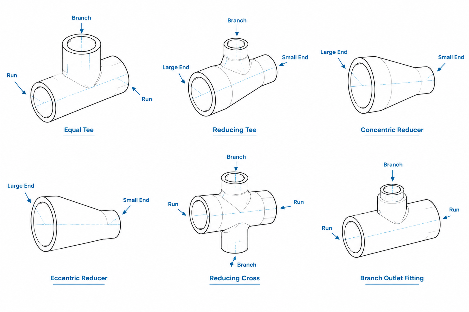
Pipe fitting size order is meaningful only when each listed size is matched to a specific port. The fitting family, connection geometry, and catalog convention determine whether a value represents a run end, branch outlet, header, or reducing end. This guide explains how to interpret those relationships and verify them across drawings, CAD models, isometrics, and bills of material.
A pipe fitting description may contain two, three, or even four nominal sizes. Reading those sizes correctly is essential because the order identifies which size belongs to each connection. A reversed or misinterpreted sequence can place the wrong fitting in a CAD model, create an incorrect material takeoff, or leave a fabricated spool unable to connect as intended.
There is no single size-order rule that can be applied blindly to every fitting family. Reducers are generally described from the larger end to the smaller end, while tees commonly identify the run before the branch. Crosses, reducing elbows, branch fittings, and specialty components may require additional interpretation. The governing piping specification, fitting standard, manufacturer data, and project catalog remain the final references.
Why Size Order Matters
Nominal sizes in a fitting description do more than identify the openings. Their sequence can communicate the fitting’s geometry and port arrangement. This affects several parts of the piping workflow:
- Catalog selection: A component must have the required size assigned to each port.
- CAD placement: The run and branch ports must connect to the correct lines.
- Isometric annotation: The displayed description must match the modeled component.
- Bill of materials: Similar-looking fittings with different size arrangements must remain distinguishable.
- Fabrication: The shop needs an unambiguous description of every connection.
- Replacement work: Each opening must match the surrounding existing piping, not merely the largest nominal size in the description.
A fitting should therefore be understood as a set of named or numbered ports, not just as a text string containing several sizes.
Common Fitting Size Sequences
| Fitting type | Common interpretation | Key check |
|---|---|---|
| Concentric or eccentric reducer | Larger end × smaller end | Confirm which end connects to each line segment and, for eccentric reducers, verify flat-side orientation. |
| Straight tee | All three openings have the same nominal size | Confirm that the item is truly equal-size rather than a reducing tee with an abbreviated description. |
| Reducing tee | Run opening × opposite run opening × branch opening is a common convention | Do not assume the two run ends are always equal; verify the catalog’s port sequence. |
| Reducing elbow | One end size × other end size, often listed larger first | Associate each size with the correct end when nearby piping sizes differ. |
| Cross | Sizes correspond to four openings according to a defined catalog sequence | Confirm the supplier or project convention because text alone may not make the opposing ports obvious. |
| Branch fitting | Run size × branch size is widely used | Distinguish the header or run size from the outlet connection size. |
| Bushing or adapter | Sizes usually identify the two different connection ends | Verify both size and end type, including male, female, threaded, socket, or other connection forms. |
These are working conventions, not substitutes for verified component data. Project catalogs may store or display the same information differently.
Reading Tee Sizes Correctly
A tee has two collinear openings forming the run and a third opening forming the branch. For an equal tee, all openings share the same nominal size, so size order normally creates little ambiguity.
A reducing tee requires more care. A common description lists the two run openings first and the branch opening last. Under that convention, a description in the form A × B × C means:
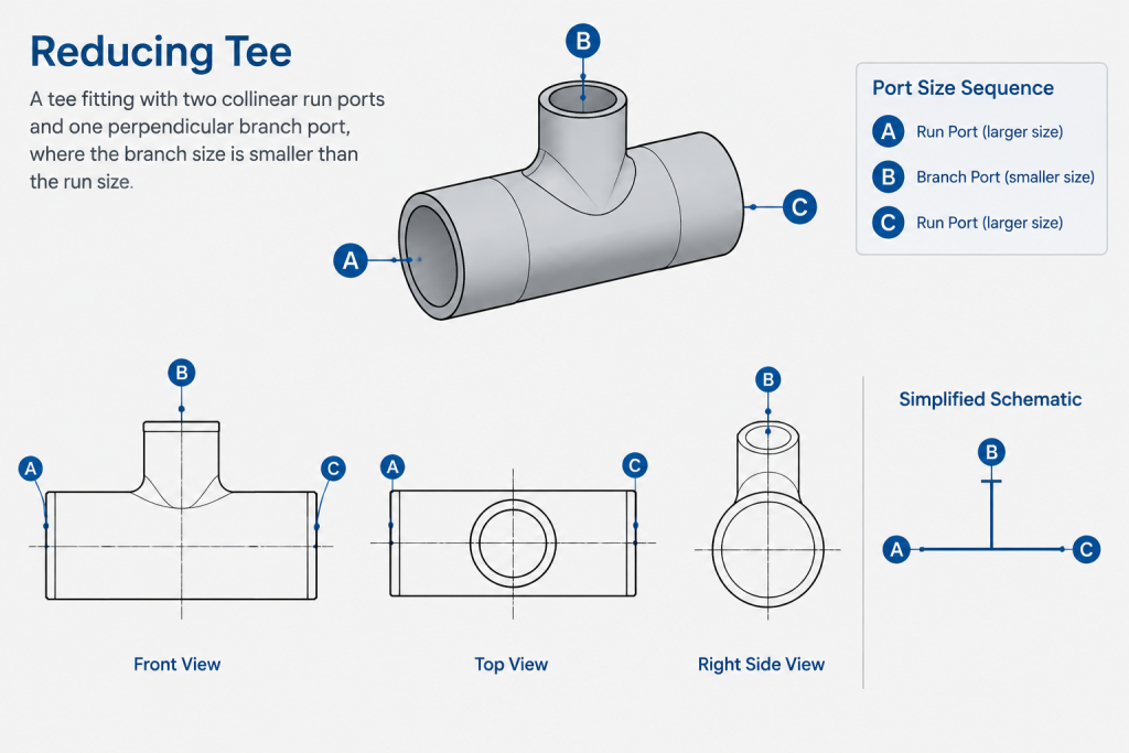
- A: one run end;
- B: the opposite run end;
- C: the branch outlet.
Many reducing tees have equal run ends and a smaller branch, which encourages users to shorten the description mentally to “run by branch.” That shortcut becomes unreliable when a catalog includes fittings with unequal run ends or uses a different field order.
In CAD, inspect the component’s port properties instead of relying only on its displayed name. Check that the two collinear ports represent the intended run and that the perpendicular port carries the branch size. Rotating a tee changes its spatial orientation, but it should not change the logical identity of its ports.
Reducers: Size Order Is Only Part of the Description
A reducer is commonly identified by its larger nominal size followed by its smaller nominal size. However, selecting the correct pair of sizes does not complete the specification.
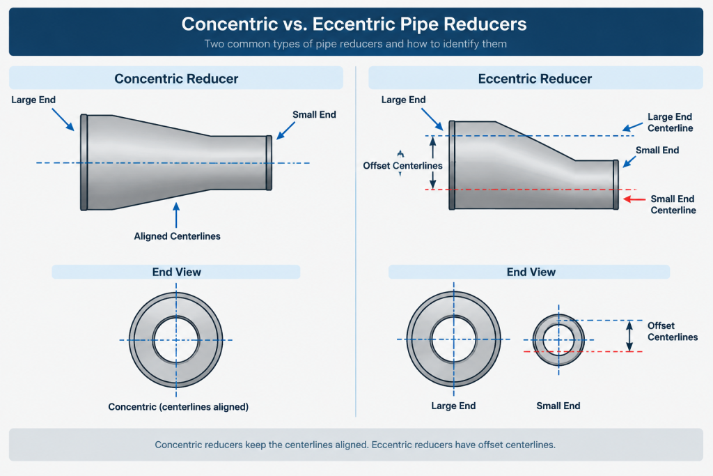
The designer must also distinguish between concentric and eccentric geometry. A concentric reducer keeps the two pipe centerlines aligned. An eccentric reducer offsets them, so its rotational orientation matters. Notes such as flat-on-top or flat-on-bottom describe installation intent, but the appropriate orientation must come from process, drainage, venting, layout, or project requirements rather than a generic drafting rule.
When a reducer appears on an isometric, verify:
- the large end connects to the larger pipe segment;
- the small end connects to the smaller segment;
- the reducer type matches the piping specification;
- the eccentric flat-side orientation is documented when relevant;
- the line size change is reflected consistently in line data, annotations, and the bill of materials.
Crosses and Other Four-Port Components
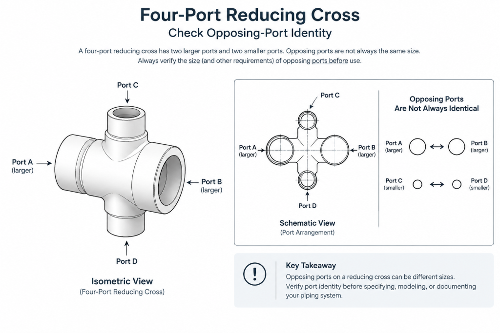
A reducing cross can be difficult to describe with text because four sizes must be associated with four physical openings. The sequence may identify one pair of opposing run ports followed by the second pair, but catalog conventions are not universal enough to infer the arrangement safely without supporting information.
For a cross with unequal openings, use a port diagram, catalog sketch, or model preview. The description should allow a reviewer to determine which sizes oppose each other. If that relationship remains unclear, the BOM description alone is insufficient for reliable fabrication.
The same caution applies to specialty manifold fittings and multi-port components. A clear port map is often more useful than a longer component name.
Branch Fittings and Header-by-Outlet Notation
Integrally reinforced branch fittings and similar outlet components are often described using the run or header size followed by the branch size. The first value identifies the pipe on which the fitting is installed; the second identifies the branch connection.
This notation can be confused with a reducer because both may display two nominal sizes. Geometry and component type resolve the difference:
- A reducer joins two coaxial pipe sizes.
- A branch fitting creates an outlet from the side of a run or header.
- An adapter changes between connection forms, sizes, or both.
The component class, connection type, and graphical representation should always accompany the size pair in a database or takeoff.
Do Not Separate Size from End Connection
Nominal size alone cannot fully identify a fitting. Each port may also have an end condition such as butt-weld, socket-weld, threaded, flanged, grooved, or another project-defined connection. A reducing adapter may deliberately have different end types, while a tee may use the same end type at all openings.
For each port, the component record should preserve at least:
- nominal size or catalog size designation;
- end-connection type;
- port role, such as run, branch, inlet, or outlet where applicable;
- applicable material or piping class data;
- component geometry and orientation properties.
This port-based approach makes automated connectivity checks more reliable and reduces dependence on abbreviated descriptions.
A Practical CAD and BOM Verification Workflow
1. Identify the fitting family
Determine whether the item is a tee, reducer, cross, elbow, branch fitting, adapter, or another component. Never interpret a pair of sizes before identifying the component type.
2. Find the port convention
Review the project catalog, symbol legend, component sketch, or manufacturer documentation to learn how ports are ordered. Record that convention if data will be exchanged between software systems.
3. Trace connected pipe sizes
Follow every connected pipe segment in the model or drawing. Each segment should meet a fitting port with the corresponding nominal size and compatible end connection.
4. Check orientation
Confirm that branches, unequal ends, eccentric offsets, and multi-port arrangements point in the intended direction. A correctly sized component can still be installed incorrectly if its orientation is wrong.
5. Compare the model and BOM
Make sure the BOM description preserves enough information to reconstruct the selected component. If two different port arrangements generate the same text, revise the description or add a port-identification note.
6. Verify against controlled data
Before issue for fabrication or construction, compare the fitting with the approved project specification and verified dimensional source. A generic CAD block or model object is a drafting aid, not evidence that the component is available or suitable.
Common Interpretation Errors
- Assuming the smallest size is always the branch size.
- Reading every two-size description as a reducer.
- Ignoring unequal run ends on a reducing tee.
- Using a cross without confirming which ports oppose each other.
- Matching nominal sizes while overlooking incompatible end connections.
- Rotating an eccentric reducer without preserving the required flat-side orientation.
- Trusting a block name when its modeled port properties indicate a different arrangement.
- Allowing different systems to export size fields in different orders without a documented mapping.
Use Port Identity as the Final Check
Pipe fitting size order is a compact communication method, but it works only when the reader understands the fitting family and the catalog’s port sequence. For routine components, familiar conventions can speed drafting and takeoff. For unequal tees, reducing crosses, adapters, and specialty branch fittings, a port-by-port check is safer than relying on habit.
The most reliable workflow combines the written size description with geometry, connection type, port identity, connected pipe data, and a verified project source. That approach keeps the CAD model, isometric, material list, and fabricated piping aligned.
Resolving an Ambiguous Fitting Description
When a size sequence is unclear, begin with the component geometry rather than trying to decode the values in isolation. Identify the collinear ports, branch ports, coaxial ends, or side outlet shown by the fitting. Then compare those physical roles with the field order used by the project catalog or supplier documentation.
Connected piping provides another useful check. A fitting port should agree with the nominal size and connection type of the adjoining pipe or component. A mismatch may indicate an incorrectly selected fitting, a reversed catalog description, an incomplete line-size change, or a data-mapping problem between design systems.
Size Order During Data Exchange
Fitting descriptions can become unreliable when information moves between a specification database, CAD platform, isometric application, and procurement system. One system may store ports by logical role, while another may export them according to an internal port identifier. A readable description should therefore be generated from a documented mapping rather than from an assumed field sequence.
For quality control, compare the displayed fitting description with the modeled port properties and graphical arrangement. If the text cannot distinguish different physical configurations, retain a port sketch, orientation note, component code, or other controlled identifier that removes the ambiguity.
What the Size Sequence Does Not Confirm
A correctly interpreted size order does not by itself establish that a fitting is appropriate for service. Material requirements, fitting geometry, end connections, piping class, manufacturing form, and project-specific restrictions must still be checked against controlled documentation. Size order identifies how openings relate to the component; it is not a complete specification.
Frequently Asked Questions
Is the first size always the largest fitting opening?
No. Reducers are commonly described with the larger end first, but other fitting families may organize sizes by run, branch, header, or catalog port sequence. Identify the component type before interpreting the order.
Which size identifies the branch of a reducing tee?
Under a common tee convention, the run openings are listed before the branch opening. Because catalog practices can differ, confirm the sequence using the project catalog, a fitting sketch, or the component’s port properties.
Why can a reducing cross be ambiguous in a bill of materials?
A text description may list every opening without clearly showing which ports oppose each other. A port diagram, model preview, or controlled catalog convention is needed when the physical arrangement cannot be reconstructed from the description.
Can the same pair of sizes describe different fitting types?
Yes. A reducer, branch fitting, adapter, or reducing elbow may each display a pair of nominal sizes. The component class, geometry, end connections, and port roles determine what the pair means.
Does rotating a fitting change its size order?
Physical rotation should not change the logical identity of the fitting ports. However, orientation still matters for branch direction, unequal ends, eccentric geometry, and other installation-dependent features.
What should be checked before releasing a fitting for fabrication?
Confirm the fitting family, port-to-size mapping, connection types, orientation, connected pipe data, bill-of-material description, and compliance with the approved project specification and verified component source.