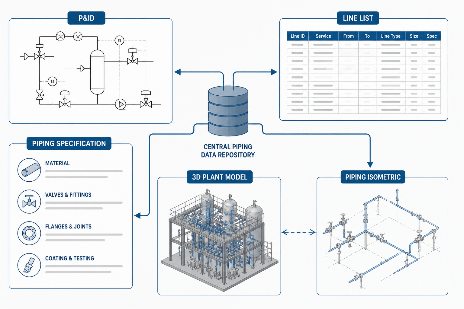
Piping document handoffs connect process intent with the information needed to model, fabricate, install, and inspect a piping system. Each deliverable presents a different view of the same design, so consistency depends on more than copying line numbers or drawing symbols between files.
This guide explains what each document contributes, where responsibilities overlap, and how engineering teams can investigate conflicts without making unsupported edits. It is especially useful for piping designers, CAD modelers, document controllers, and reviewers who need to trace a change from process definition through construction documentation.
Piping design rarely depends on a single drawing or database. A process engineer may define the service on a P&ID, a line list may carry the design conditions, a piping specification may control component selection, and a CAD model may establish the physical arrangement. The isometric then turns that coordinated information into a fabrication and installation document.
These documents are related, but they are not interchangeable. Each has a different purpose, level of detail, and responsibility for communicating design intent. Treating them as copies of one another is a common cause of missing valves, incorrect line attributes, inconsistent tags, and avoidable rework.
Why piping document handoffs matter
A handoff occurs whenever information moves from one design deliverable or discipline to another. For example, a process requirement may move from a process flow diagram into a P&ID, then into a line list and piping model. The model may generate an isometric, while equipment and structural teams use the same arrangement to coordinate nozzles, platforms, and supports.
Problems occur when the receiving document captures only the geometry and not the meaning behind it. A line may appear correctly routed in CAD while carrying the wrong service, material class, insulation status, or test boundary. Conversely, a P&ID may show the intended function without defining the physical arrangement needed for fabrication.
Good handoffs preserve three types of information:
- Functional information: what the line or component does in the process.
- Physical information: where the line is located and how components connect.
- Control information: how the item is identified, checked, revised, and approved.
What each piping document is meant to control
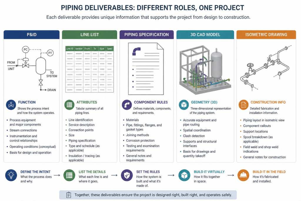
| Document | Primary purpose | Information it commonly provides | Information it usually does not replace |
|---|---|---|---|
| P&ID | Communicate process function and piping logic | Equipment connections, valves, instruments, flow paths, drains, vents, and control relationships | Final routing, fabrication dimensions, support design, or complete material quantities |
| Line list | Organize line-level design data | Line number, service, size designation, material class, design conditions, insulation, and test-related attributes | Detailed geometry, component orientation, and field installation sequence |
| Piping specification | Define permitted component and material selections | Pipe, fittings, flanges, valves, gaskets, bolting, branch components, and end-connection rules | Process intent or the actual route of a particular line |
| 3D CAD model | Coordinate physical arrangement | Routing, elevations, component placement, nozzle orientation, clearances, supports, and spatial interfaces | Complete process logic or final authority for unapproved design inputs |
| Isometric drawing | Document a line or spool for review, fabrication, or installation | Connectivity, dimensions, welds, components, material identification, and construction notes | Plant-wide arrangement or process control logic |
Project procedures can assign different ownership or document statuses, so the table should be treated as a practical framework rather than a universal document hierarchy.
How information normally moves through the workflow
1. Process definition becomes a P&ID
The P&ID establishes why a line exists and how it relates to equipment and process controls. It may identify isolation valves, control valves, relief devices, drains, vents, instruments, and special operating arrangements. At this stage, symbols and connections communicate function more than physical scale.
A CAD modeler should not infer missing process functions from geometry alone. If a line appears to require a drain, bypass, or isolation point, that question should be returned to the responsible design team rather than silently added or omitted.
2. Line-level data becomes structured information
The line list translates design information into attributes that can be filtered, checked, and transferred between systems. A line number may connect the P&ID, line list, model, isometric, material takeoff, and inspection records. Other attributes can include nominal size, material class, fluid service, design conditions, insulation, tracing, and test information.
Line lists are especially useful for identifying data that is easy to miss in a drawing review. They also expose conflicts early. For example, a model may show an insulated line while the line list shows no insulation requirement, or an isometric may contain a component that does not match the assigned material class.
3. The piping specification constrains component choices
The piping specification is the bridge between line attributes and component selection. It defines which materials, pressure classes, end connections, valves, fittings, and joining methods are permitted for a particular service or material class.
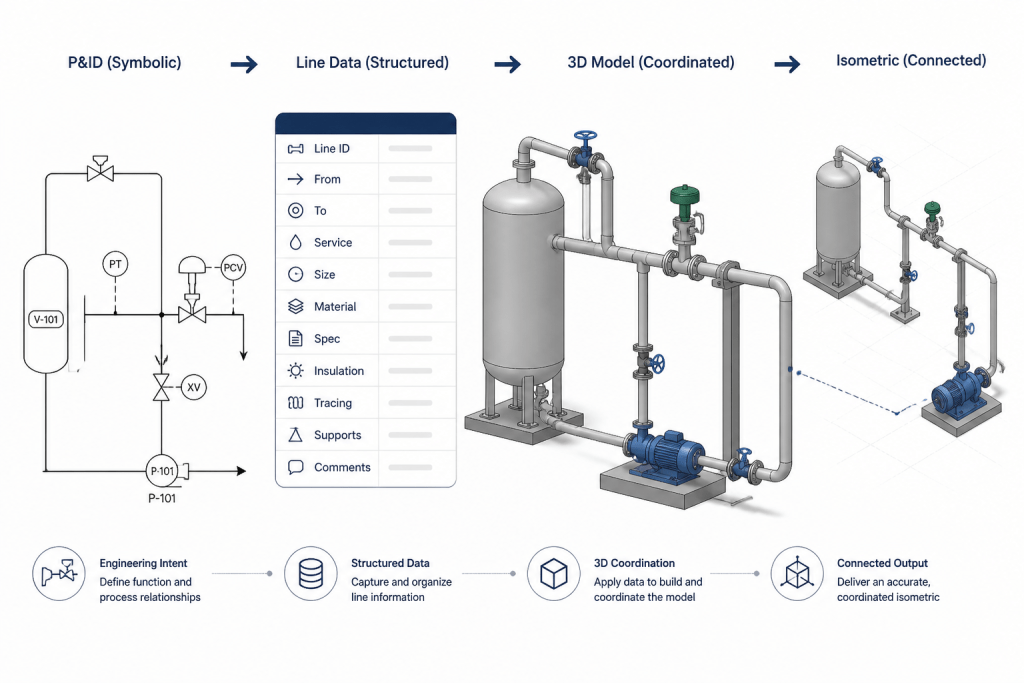
It is important to distinguish a line’s assigned specification from the geometric library item used in CAD. A library block may look correct but contain the wrong face-to-face dimension, end type, rating designation, or connection representation. Modelers should verify that the selected component carries the intended specification data, not just the correct visual shape.
4. The CAD model develops the physical arrangement
The model converts abstract connections into a coordinated route. It must account for equipment nozzles, access, supports, structures, insulation, maintenance space, fabrication preferences, and interfaces with other disciplines. The model also reveals issues that are difficult to see in a symbolic document, such as an inaccessible valve, a flange that cannot be bolted, or a route that conflicts with structural steel.
Model geometry should remain traceable to the line and component identifiers established upstream. When a route is split, rerouted, or divided into fabrication sections, the change should not break the relationship between the original line and its downstream deliverables.
5. The isometric communicates construction information
An isometric extracts a line or defined portion of the model into a document that can be reviewed, fabricated, installed, and inspected. It adds dimensions, weld identification, component callouts, material information, and notes that may not be necessary in the overall model.
The isometric is not simply a plotted 3D view. It is a controlled interpretation of the model. If the drawing shows a branch, valve, or weld that is absent from the model database, the discrepancy can affect material quantities, fabrication, and inspection records.
Common handoff conflicts
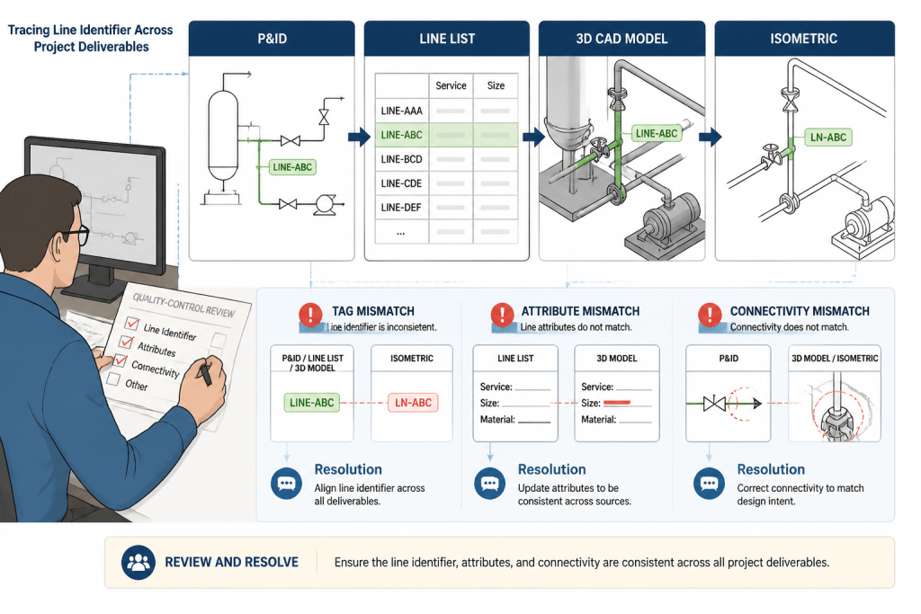
- Tag mismatch: the same valve, line, or equipment nozzle has different identifiers in different documents.
- Attribute mismatch: size, material class, insulation, tracing, or service data differs between the line list and model.
- Connectivity mismatch: the P&ID shows a connection that the CAD model does not contain, or the model includes an unapproved branch.
- Representation mismatch: a component is visually present but lacks the correct metadata, connection points, or bill-of-materials identity.
- Revision mismatch: one deliverable reflects a design change while another remains at an earlier status.
- Ownership ambiguity: reviewers cannot tell whether process, piping, equipment, or vendor information controls a disputed item.
A practical conflict-resolution workflow
Start with the smallest affected object
Do not begin by comparing entire drawings visually. Isolate the affected line, component, nozzle, or branch. Confirm its identifier, document status, and revision before comparing attributes or geometry.
Separate fact from interpretation
Record what each document actually states. Then identify the design question that remains unanswered. For example, “the line list assigns one material class and the model assigns another” is a factual observation. “The model should control” is an interpretation that requires project ownership rules.
Check upstream intent before editing geometry
When an isometric or model conflicts with a P&ID, do not correct the drawing by assumption. Confirm whether the P&ID is current, whether a change notice exists, and whether the line was intentionally split or rerouted. A local CAD edit can hide a process or specification issue rather than solve it.
Update linked deliverables together
Once the responsible discipline resolves the issue, update the affected database records, model objects, drawings, and review notes. A corrected model with an outdated line list is still an incomplete handoff.
How to make handoffs more reliable in CAD
- Use stable identifiers for lines, components, welds, equipment, and nozzles.
- Keep required data fields consistent across the line list, CAD database, and drawing output.
- Distinguish design status from graphical completeness; a detailed model can still contain unapproved information.
- Use model reports and targeted comparisons to find attribute differences, not only visual clashes.
- Record the source and revision of vendor data before incorporating it into the model.
- Make unresolved assumptions visible through review comments, hold points, or controlled status fields.
Final perspective
Piping documents work best as connected views of one controlled design, not as independent copies. The P&ID explains function, the line list organizes attributes, the specification constrains component choices, the CAD model coordinates space, and the isometric communicates construction information. Clear ownership and traceable identifiers allow those views to remain consistent as the design develops.
For CAD teams, the most useful habit is to ask two questions whenever information changes: what design intent does this item represent, and which other deliverables depend on it? That approach turns document handoffs from a source of surprises into a deliberate part of piping quality control.
How to read a coordinated piping document set
A reliable handoff preserves meaning as information becomes more detailed. The P&ID communicates process behavior and operating relationships. The line list organizes line-level attributes for checking and transfer. The piping specification limits the component choices that may be used. The CAD model develops the physical arrangement, while the isometric presents selected construction information in a controlled drawing format.
These roles create useful checks between documents. A line identifier should lead reviewers to the corresponding process representation, line attributes, model objects, and drawing output. A valve shown in the process documentation should also be traceable to the selected component, its modeled location, and its construction representation. The exact ownership of each item depends on project procedures, but the need for traceability remains.
A practical review sequence
- Confirm identity: verify the line, component, nozzle, or branch identifier and document revision.
- Confirm purpose: determine whether the item is being reviewed for process function, data attributes, physical arrangement, or construction output.
- Compare attributes: check service, material class, insulation, tracing, connection information, and other required fields against the applicable source.
- Compare connectivity: confirm that branches, valves, drains, vents, instruments, and equipment interfaces agree with the approved design intent.
- Check physical coordination: review access, clearances, support interfaces, nozzle orientation, and fabrication implications in the model and isometric.
- Resolve by ownership: separate documented facts from assumptions and route unresolved decisions to the responsible discipline.
Why geometry alone is not enough
A visually complete CAD model can still contain missing metadata, an incorrect material assignment, an outdated revision, or an unapproved design assumption. Likewise, a complete-looking isometric can conceal a mismatch with the current line list or process documentation. Effective review therefore combines graphical inspection with attribute comparison, revision control, and a clear record of design decisions.
When a change affects more than one deliverable, treat the update as a coordinated transaction rather than a local drafting correction. Identify the affected records, confirm the approved source, update dependent outputs, and leave unresolved questions visible until the responsible team closes them.
Frequently asked questions
What is a piping document handoff?
A piping document handoff is the controlled transfer of design information from one deliverable, discipline, or system to another. It may involve process intent, line attributes, component selection, physical arrangement, or construction documentation.
Is the P&ID the same as the piping model?
No. A P&ID primarily communicates process function, equipment relationships, valves, instruments, and piping logic. A piping model develops the physical route, component placement, access, clearances, and interfaces needed for coordinated design.
What information does a line list add to the workflow?
A line list organizes line-level information in a structured form that can be filtered, checked, transferred, and compared. It helps reviewers identify differences in service, material class, insulation, tracing, design inputs, and testing attributes.
Why can a CAD component look correct but still be wrong?
A graphical library item may have the expected appearance while carrying incorrect metadata, connection information, dimensions, end conditions, or material identity. Component selection must therefore be checked against the applicable piping specification and project data.
What should be done when an isometric conflicts with a P&ID?
First isolate the affected line or component and confirm the revision status of both documents. Then determine whether the difference results from an approved change, a deliberate line split, an outdated deliverable, or an unresolved design issue. Do not correct the drawing by assumption.
Which document controls when project documents disagree?
There is no universal answer. Project procedures, document status, discipline ownership, approved changes, vendor information, and design responsibility determine which source governs a particular question. The conflict should be recorded and resolved through the project’s established review process.