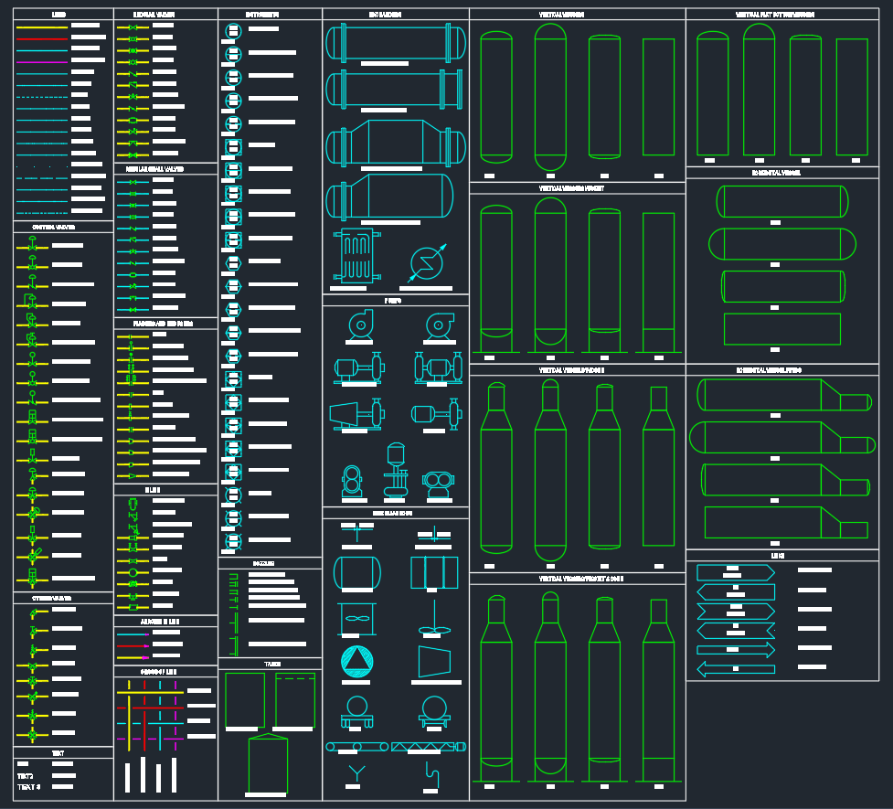
Clear P&ID documentation depends on more than recognizing individual icons. Designers must also understand how equipment, piping, valves, instruments, tags, and signal paths work together as a process record. This P&ID symbols DWG resource provides a practical starting point for drafting and reviewing process and instrumentation diagrams in CAD.
Use the existing symbol explanations below alongside the project’s drafting conventions, line lists, equipment references, and instrumentation documentation. For related drafting work, the PipeSTD references for pipe dimensions and schedules, pipe fittings, flanges, and piping terminology can help connect diagram information with piping design data.
P&ID Symbols are essential graphical representations used in engineering drawings to describe process systems in industries such as oil and gas, chemical plants, power generation, and manufacturing. These symbols provide a universal method for engineers and designers to communicate how equipment, instruments, and pipelines are interconnected within a process. A well-drafted P&ID (Piping and Instrumentation Diagram) ensures efficient design, accurate construction, and effective maintenance.
Introduction
A P&ID (Piping and Instrumentation Diagram) is a detailed schematic that displays the piping layout and associated instrumentation of a process system. It shows every valve, pump, pipeline, and sensor used in a plant’s operation. P&ID symbols are standardized graphical icons that make it easier to interpret and create these diagrams accurately. Common standards include ISA S5.1 and ISO 10628, which define consistent symbol usage across different engineering disciplines.
Key Components of P&ID Symbols
P&ID symbols are grouped according to the type of component they represent. Below are some of the most frequently used categories:
1. Process Equipment Symbols
These include symbols for essential industrial equipment such as pumps, compressors, heat exchangers, tanks, and reactors. Each symbol provides details like equipment type, function, and connection points. For example, a centrifugal pump symbol shows suction and discharge nozzles, while a heat exchanger symbol indicates tube and shell flow paths.
2. Valve Symbols
Valves control the flow of fluids in a process system. Common symbols include gate valves, globe valves, ball valves, butterfly valves, and check valves. Specialized control valves are also shown with actuators and positioners to indicate automation or manual control.
3. Instrumentation Symbols
Instrumentation symbols represent measuring and control devices such as pressure gauges, flow transmitters, temperature sensors, and control loops. Each instrument has a unique tag number that helps identify its role within the control system. These symbols help engineers understand how the process is monitored and controlled.
4. Piping and Line Symbols
Piping symbols define how different lines connect between components. They include representations for pipes, fittings, elbows, reducers, tees, and line numbers. Line types also vary based on service, such as process lines, instrument air, or utility connections.
5. Control and Signal Lines
Control lines in P&IDs indicate how signals flow between instruments and controllers. Different line styles (solid, dashed, dotted) represent various types of signals such as pneumatic, hydraulic, electrical, or digital communication.
How to Use P&ID Symbols in CAD Drawings
When creating a P&ID drawing in AutoCAD or any CAD software, using standardized P&ID symbols ensures clear communication among engineering teams. Most designers use preloaded symbol libraries in DWG format to speed up the process. Symbols can be inserted directly into a drawing to build a system layout efficiently.
Here’s how to use P&ID symbols effectively:
- Start with a template: Use a base drawing with predefined layers for lines, equipment, and annotations.
- Insert symbols: Drag and drop standardized P&ID symbols into your drawing using CAD blocks or tool palettes.
- Tag components: Assign identification tags to each element for easy reference during construction or maintenance.
- Maintain consistency: Follow project-specific or international standards (ISA, ISO, or DIN) to keep symbols uniform.
- Cross-check connections: Ensure that every instrument and line has a logical connection path to avoid design errors.
Download Section
For professionals creating process schematics, having a reliable library of P&ID symbols in AutoCAD DWG format saves time and ensures accuracy. This collection includes symbols for pumps, valves, fittings, instruments, tanks, and other essential components used in industrial design.
Conclusion
P&ID symbols are a vital part of process design and documentation in mechanical, electrical, and instrumentation engineering. By using standardized and well-organized symbols in DWG drawings, engineers can communicate design intent clearly across teams and disciplines. Whether you are designing a new plant or updating an existing one, accurate P&ID symbols ensure reliability, clarity, and compliance with engineering standards. Download a complete DWG set to enhance your workflow and produce professional, ready-for-review P&ID drawings with confidence.
Reading a P&ID Before Drafting
A P&ID is primarily a communication and documentation tool. It shows functional relationships rather than the physical appearance or exact installed location of every item. A line may represent a process connection, utility service, or instrument signal, while tags and notes provide the identity needed to trace that item through design, construction, operation, and maintenance records.
Trace the process path
Begin with the main process flow and follow each connection through equipment and valves. Check that branches, isolation points, drains, vents, and other connected items are represented consistently with the project’s drawing practice. The symbol itself is only part of the information; line identification, tags, notes, and connection details also affect how the drawing is interpreted.
Separate physical lines from signals
A process or utility line represents a fluid connection, while a control or signal line represents communication between an instrument, controller, actuator, or related device. Reviewing these paths separately makes it easier to distinguish what carries process material from what measures, controls, or reports process conditions.
Use DWG blocks carefully
CAD blocks improve drafting speed, but a downloaded block should be checked before it is added to a controlled project drawing. Confirm its insertion behavior, layer assignment, orientation, attribute or tag fields, connection points, and visual consistency with the project template. A symbol library should support the project convention rather than silently introduce a different drafting method.
Useful related references
After identifying a line or component on the P&ID, use the site’s references for pipe dimensions and schedules, fittings, and flanges when preparing related piping documentation. The piping terminology reference is also useful when reviewing notes, line descriptions, and coordination comments. These references support interpretation; final selection and design remain subject to the project specification and engineering review.
Frequently Asked Questions
What does a P&ID symbol represent?
A P&ID symbol is a graphical representation of process equipment, a valve, an instrument, a piping item, or a connection. Its meaning is interpreted together with tags, line types, notes, and the project legend.
What is included in a P&ID symbols DWG library?
A DWG library may include reusable CAD blocks for equipment, valves, fittings, instruments, tanks, and related diagram elements. The available content depends on the specific library, so review the file before using it in a controlled drawing set.
Are P&ID symbols the same as physical equipment drawings?
No. P&ID symbols communicate process function and relationships. They are not normally a substitute for equipment arrangement drawings, fabrication drawings, piping isometrics, or manufacturer documentation.
Why are tags important on a P&ID?
Tags provide a consistent way to identify equipment, valves, instruments, and other items. They help users trace an item between the P&ID and associated engineering, procurement, construction, operation, and maintenance records.
Should every DWG symbol be used without modification?
No. Check the symbol against the project legend, CAD standards, layer structure, annotation rules, and required attributes before use. A technically recognizable symbol can still create coordination problems if it does not match the controlled drawing convention.
What should be checked during a P&ID review?
Reviewers commonly trace process and signal paths, check tags and line identifiers, confirm that connected items are represented consistently, and compare the drawing with the applicable project documents. The review should also verify that the symbols and annotations follow the project’s adopted conventions.