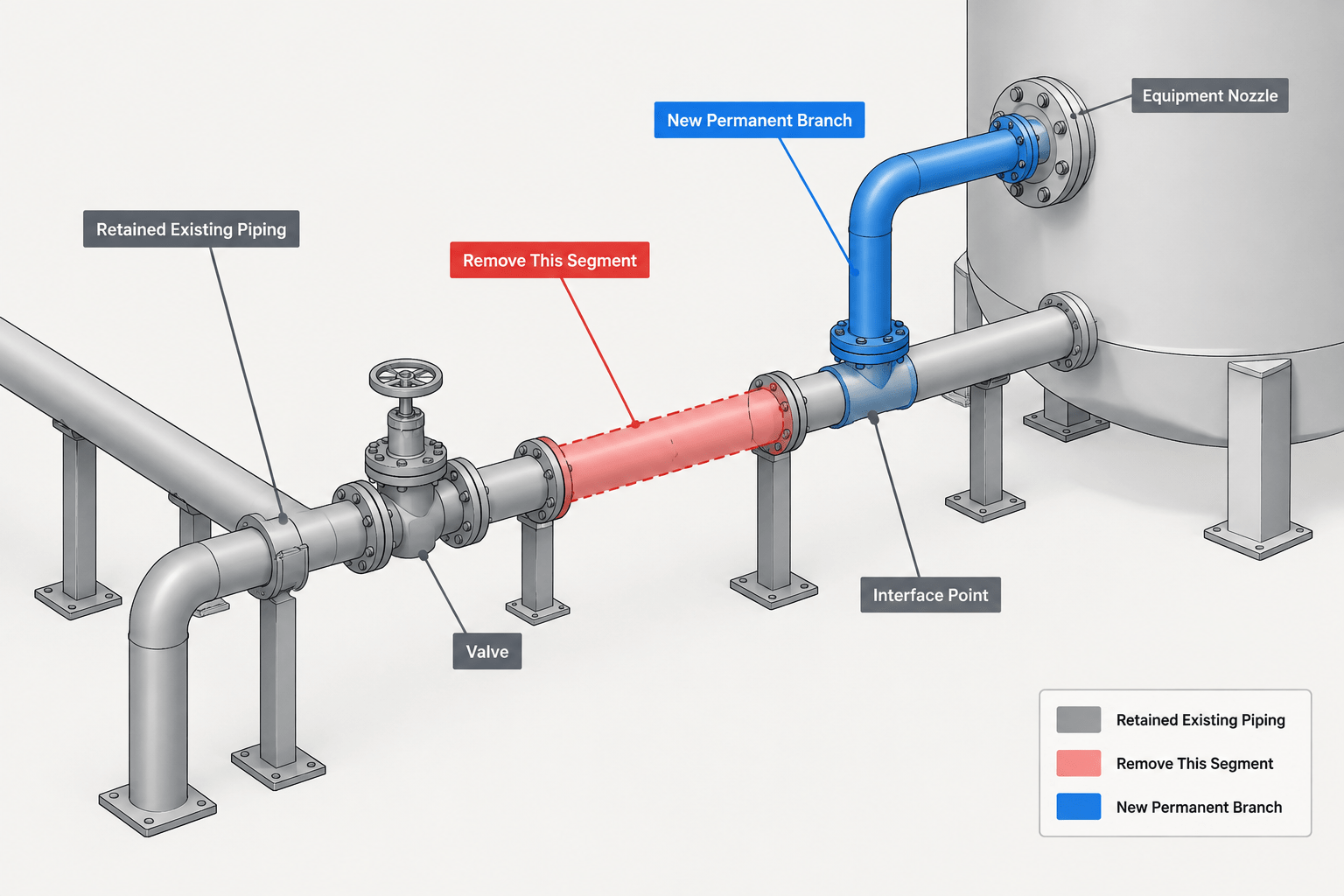
Existing, demolition, and temporary piping in CAD must be documented as distinct project conditions, not merely drawn as variations of the same pipe route. Clear status information helps project teams understand the transition between the plant or facility as found and the intended permanent arrangement.
This guide explains a practical documentation workflow for representing retained piping, removal scope, new permanent work, and short-term piping arrangements. The goal is to make drawing intent understandable across model views, plans, sections, isometrics, and closeout records.
Piping projects rarely begin with an empty model. A new line may connect to an operating header, replace a damaged segment, bypass equipment during construction, or reuse portions of an existing system. In these situations, CAD drawings must do more than show the final routing. They must communicate what is already present, what will be removed, what is temporary, and what must remain in service.
That distinction is essential for designers, field crews, estimators, construction planners, and operations personnel. A drawing that makes the final arrangement look clear but does not clearly describe the transition from the current condition can create avoidable uncertainty at the tie-in location. Good documentation turns a complex sequence of modifications into a coordinated set of graphic instructions.
Why status is as important as geometry
A pipe run can have correct coordinates, components, and dimensions while still being poorly documented. If its installation status is unclear, reviewers may not know whether it is included in the new scope, retained from an earlier project, removed before construction, or installed only for a temporary operating condition.
Status affects decisions throughout the project:
- Design coordination: Existing items may constrain new routes, support locations, access paths, and equipment maintenance space.
- Construction planning: Demolition limits and temporary connections influence work sequencing, isolation planning, and outage preparation.
- Estimating: Material takeoffs should distinguish new materials from existing components that are shown only for context.
- Operations review: Operations teams need to understand which lines remain active during each phase of the work.
- As-built documentation: A future drawing set should make it possible to identify the final installed condition without confusing it with superseded temporary work.
The key principle is simple: geometry says where an item is; status says what happens to it.
Define a project-wide status vocabulary first
Before modeling or drafting, establish a limited and consistent set of status categories. The exact vocabulary varies by owner and project, but the drawing team should agree on the meaning of each category before views, layers, and tags are produced.
| Status | Typical drawing meaning | Common coordination question |
|---|---|---|
| Existing to remain | Currently installed item that stays in service or remains physically in place. | Does the new work clear it and preserve access? | Existing to be removed | Installed item included in demolition or abandonment scope. |
| What are the exact removal limits and affected connections? | ||
| New permanent | New item intended to remain after the project is complete. | Is it fully identified, supported, and connected to the correct system? | Temporary | Item installed for a limited construction, commissioning, bypass, flushing, or operating condition. |
| When is it installed, and when is it removed or isolated? | Future or reserved | Potential work not included in the current installation scope. |
| Is it informational only, or does it require a physical allowance now? |
Do not use terms such as existing, new, and temporary casually in different ways across the drawing set. For example, an existing pipe may be physically retained but abandoned from service. That condition needs a separate, explicit treatment rather than a generic existing-line graphic.
Use more than one visual cue
A status should never depend on color alone. Drawings may be printed in monochrome, viewed on different displays, exported to PDF, or used by a field team working from marked-up paper copies. Color can support communication, but it should not carry the entire meaning.
A reliable graphic system combines several cues:
- Layer or object classification: Separate model objects by status so views can be filtered and checked.
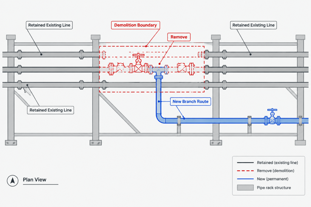
- Line type and line weight: Use a project-defined graphic distinction between retained, removed, and new work.
- Tags: Include status where it is needed to prevent ambiguity, especially at connection points and limits of work.
- Legends: Explain all status graphics in a visible, consistent location.
- Notes and keyed callouts: State the intended action where graphics alone cannot explain the sequence.
- Revision clouds or phase boundaries: Use these carefully to identify changed areas without obscuring the underlying piping information.
In a 3D model, object properties should also support the visual system. A reviewer should be able to isolate new permanent piping, hide demolition items, or display temporary work independently. This is especially useful when producing construction sequence views.
Show limits of removal and limits of new work precisely
Demolition drawings are most useful when they identify the exact point at which an existing system changes status. A vague cloud around a congested area is not a substitute for a defined removal limit.
At every demolition boundary, clarify the physical action. Depending on project scope, that may include removing a component, cutting back a line, capping an end, installing a blind, preparing an end for a future connection, or leaving a pipe in place after isolation. The drawing should not assume that the person reading it can infer the intended action from a discontinuity in the linework.
Similarly, a new-work boundary should identify where new piping begins. At a tie-in, show the relationship between the new item and the retained existing item. Include applicable line identification, connection type, and orientation information, while leaving process isolation, safety planning, and final field execution decisions to the responsible project disciplines.
Avoid the “floating new pipe” problem
A common drafting issue occurs when a new line begins near an existing header but the connecting scope is unclear. The plan view may look connected, yet the isometric, demolition plan, and piping and instrumentation diagram may tell different stories. Prevent this by treating every interface as a documented node:
- Identify the existing line or nozzle being approached.
- Show whether the existing portion remains, is modified, or is removed.
- Identify the new component or new line segment beginning at the interface.
- Reference the governing tie-in or construction package information when applicable.
- Check that all related views use the same status designation.
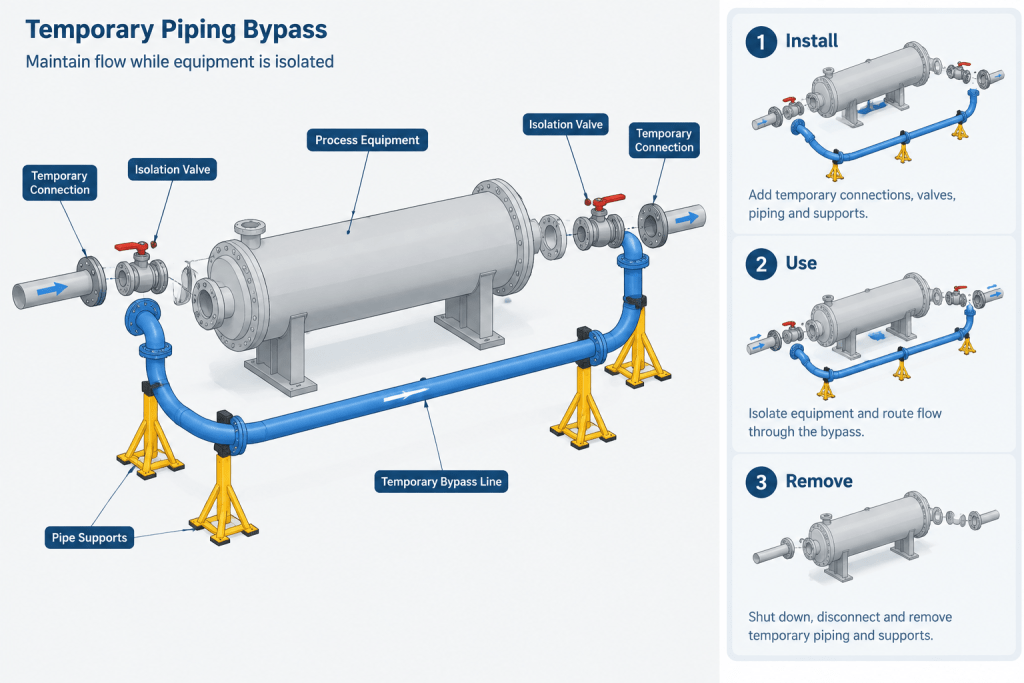
Temporary piping needs a lifecycle, not just a different line style
Temporary piping is often overlooked because it may not appear in the final plant configuration. However, it can drive important layout and coordination decisions while it is in use. A temporary bypass, drain connection, test arrangement, or commissioning line can occupy access space, cross a work area, require supports, or interfere with permanent installation sequencing.
Document temporary piping as a lifecycle:
- Purpose: State why the temporary arrangement exists, such as bypassing a component or supporting a construction activity.
- Installation condition: Show where it connects and what permanent or existing items must be in place first.
- Operating duration: Identify the project phase or event that governs its use without implying a detailed operating procedure.
- Removal or disposition: State whether the temporary assembly is removed, retained, converted, or replaced after its function is complete.
A temporary line should also be excluded from permanent material reports unless the project workflow intentionally tracks it in a separate temporary-works package. This avoids a bill of materials that mixes final installed components with short-term construction equipment.
Coordinate the same story across drawing types
Status information must remain consistent between plans, sections, isometrics, piping and instrumentation diagrams, demolition packages, and model views. Each deliverable has a different job, but they should describe the same physical transition.
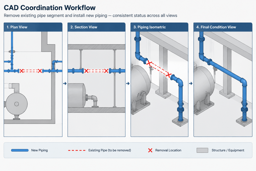
For example, a plan may best show the extent of removal in a crowded rack. An isometric may better communicate a cutback location, component sequence, and fabrication-related detail. A section may reveal an elevation conflict with retained pipe or steel. A line list or model property set may distinguish a new line from an existing line with a similar service description.
Use a focused coordination review whenever a drawing includes multiple statuses. Compare the following items:
- Line identifiers and component tags at every interface.
- Removal limits shown in plan, section, and isometric views.
- New permanent routing against retained existing geometry.
- Temporary piping against access routes, support locations, and construction space.
- Material reports to confirm that only intended scope items are included.
- Legends, notes, and layer names to confirm that they use the agreed status vocabulary.
Build final-condition views for long-term usefulness
Construction drawings often need to show existing, demolition, temporary, and new work at once. That is appropriate for execution, but it can become difficult to use after the project is complete. Create or preserve a final-condition view that shows the intended permanent arrangement without obsolete temporary work or removed piping competing for attention.
This does not mean deleting historical information from controlled project records. Instead, it means organizing model objects and drawing views so each audience can see the condition relevant to its task. Construction teams need transition information. Operations and future designers need an intelligible record of what remains.
Practical review checklist
- Can a reviewer identify the status of every pipe segment without relying only on color?
- Are existing retained, removal, new permanent, and temporary items separated in the model or drawing organization?
- Are tie-ins and demolition boundaries explicitly shown rather than implied?
- Do notes explain the required physical action at cutbacks, caps, and isolated ends?
- Are temporary piping installation and removal conditions documented?
- Do plan, section, isometric, and diagram views tell the same status story?
- Can the final permanent arrangement be viewed without temporary or removed work creating confusion?
Clear status documentation does not replace detailed construction planning, operating procedures, or project-specific safety review. It does provide the shared spatial record those activities depend on. When CAD models and drawings make the existing-to-new transition visible, teams can review scope boundaries earlier, coordinate more reliably, and preserve a more useful record of the completed piping system.
How to apply the workflow in a live CAD environment
The most effective status-documentation system begins before detailed routing. Establish status definitions, model properties, layer conventions, annotation practices, and deliverable expectations as part of project setup. When those decisions are deferred, the team may create visually similar objects that require extensive rework before issue.
For each pipe segment, component, or connection, maintain a clear distinction between its physical condition and its project action. A component can be physically present in the field while being scheduled for removal, retained in place but isolated, or shown only as contextual geometry. Treating these as separate questions helps prevent ambiguous use of a single existing-piping category.
Use status properties that support checking
Model classification is valuable because it makes status information searchable and reviewable rather than dependent only on drafting appearance. A project team can use its approved CAD or model-data fields to identify the status of an object, the applicable phase, and any associated tie-in or work-package reference. The graphics shown on a sheet should then be generated or checked against that underlying classification.
- Use a controlled status field rather than relying on free-form notes wherever the project system supports it.
- Apply the same classification to associated components, not only the pipe centerline or route.
- Review branches, valves, supports, and specialty items near a status boundary so their scope is not implied incorrectly.
- Preserve enough existing context to evaluate interfaces, while avoiding unnecessary background geometry that hides the work.
Make interfaces traceable during review
A tie-in is an interface between defined conditions, not simply a point where two lines touch on screen. The drawing record should let a reviewer follow the transition from retained piping through modification work and into new piping without guessing which party or package owns each action. This is especially important where demolition, temporary connections, and permanent installation occur in the same area.
During interdisciplinary review, compare the visible status graphics with model properties, line identification, notes, and material-report inclusion. A mismatch can reveal issues such as a demolition item appearing in a permanent report, a temporary item remaining visible in a final-condition view, or a retained line that is accidentally hidden by a view filter.
Recommended deliverable strategy
Use purpose-specific views rather than forcing every audience to interpret a single crowded drawing. A construction-oriented view may need all relevant statuses and transition notes. A demolition view should emphasize removal extent and required end conditions. A final-condition view should prioritize the permanent record. These views can reference the same coordinated model while presenting only the information needed for their respective decisions.
Before issue, conduct a status-focused quality review at areas of change. Verify that each boundary has an explicit action, each temporary arrangement has a documented disposition, and each final-condition view excludes work that will not remain. This discipline improves handoff to construction and leaves future maintenance, modification, and as-built efforts with a more reliable starting point.
Frequently Asked Questions
What is the difference between existing piping and existing piping to be removed?
Existing piping describes an item already installed at the time of the project. Existing piping to be removed is a defined subset of that installed condition that is included in demolition or abandonment scope. The drawings should distinguish retained items from removal items clearly.
Why should temporary piping be modeled or drawn separately?
Temporary piping can affect access, support coordination, routing, work sequencing, and tie-in planning even though it is not part of the final facility condition. Separate classification and views help prevent it from being mistaken for permanent work.
Can color alone identify demolition and new piping?
No. Color can reinforce the intended meaning, but monochrome printing, display settings, and field copies can remove that distinction. Combine color with approved line conventions, tags, notes, legends, and model classification.
What should a final-condition CAD view include?
A final-condition view should show the intended permanent piping arrangement and the retained items needed to understand it. Removed and temporary work should not compete with the final record, although controlled project documentation should retain the historical construction information separately.
How can a team check status consistency across drawings?
Review each tie-in, removal limit, and temporary connection across plans, sections, isometrics, diagrams, model views, and material reports. Confirm that identifiers, status graphics, notes, and object classifications describe the same scope transition.