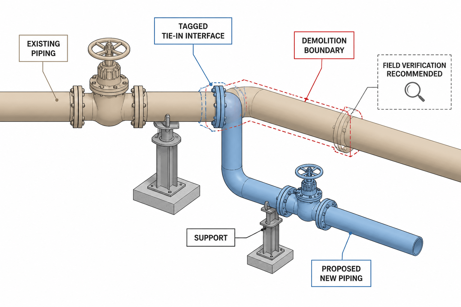
Clear piping tie-in documentation is essential whenever a proposed modification meets an installed system. The CAD drawing must do more than show where lines appear to meet: it must identify the interface, establish the work boundary, expose uncertainty, and support coordination among design, field verification, operations, and construction teams.
This guide explains a practical workflow for reviewing tie-in points in plan views, elevations, sections, isometrics, spool drawings, and schedules. It also shows how consistent identifiers and disciplined existing-versus-new conventions reduce interpretation errors without overstating the accuracy of record information.
Piping tie-in points are the locations where new piping connects to an existing line, equipment nozzle, utility header, or other installed system. In CAD, a tie-in is more than a break in a line. It is a coordination point that connects design information, field verification, construction planning, isolation requirements, and the limits of the new work.
Poorly documented tie-ins can create ambiguity about what is existing, what is being removed, where the connection will be made, and which dimensions must be confirmed in the field. A clear tie-in workflow helps the CAD designer show the proposed work without pretending that incomplete existing-condition information is exact.
What a piping tie-in represents
A tie-in identifies the interface between an existing system and a proposed modification. The connection may be made by welding, bolting, flanging, threading, or another approved method defined by the project requirements and piping material specification. The drawing should communicate the interface clearly, but the final connection method must come from the responsible engineering and construction documents.
A tie-in may occur at several common locations:
- An existing straight pipe run
- An existing branch connection or header
- An equipment nozzle or vessel connection
- A valve, flange, blind, or other removable component
- A utility connection at a battery limit or unit boundary
- A temporary connection used during construction or commissioning
The term may also be used for the work boundary itself. For example, a drawing can identify a tie-in point while separately showing the demolition limit, field weld location, or installation boundary. These items should not be assumed to be identical.
Separate existing, new, and uncertain information
The first CAD task is to distinguish the condition that is known from the condition that is proposed. Existing piping may come from older drawings, laser scans, field sketches, survey data, or plant records. These sources can differ in accuracy, level of detail, and revision status.
Use a consistent visual and layer strategy for the following categories:
| Information category | Typical drawing purpose | Review question |
|---|---|---|
| Existing piping | Shows the system that remains in place | Is the source and revision status known? |
| New piping | Shows the proposed route and components | Does the new work connect to the correct interface? |
| Removal or demolition | Shows items to be removed, cut, or abandoned | Is the removal limit unambiguous? |
| Field-verified information | Identifies dimensions or conditions requiring confirmation | Is the verification responsibility clear? |
| Reference or background geometry | Provides context without implying construction scope | Could a contractor mistake it for new work? |
Do not use line weight or color as the only method of communicating these distinctions. Printed drawings, monochrome PDFs, and exported CAD files can remove visual differences. Combine graphical conventions with notes, tags, legends, and clear line descriptions.

Locate the tie-in using reliable references
A tie-in should be located from references that another person can check. Useful references include equipment tags, line numbers, valve tags, structural grid lines, column lines, building coordinates, known pipe supports, and drawing coordinates. A vague note such as “connect to existing line nearby” is difficult to verify and can lead to field interpretation.
When the existing line is shown on an orthographic drawing, identify the relevant pipe segment and its direction. On an isometric, show enough surrounding geometry to distinguish the intended connection from nearby branches or parallel lines. If the connection is close to a component, identify the component and its orientation rather than relying on a crowded leader line.
For a tie-in on a live or operating system, the design package may also need information about access, isolation, drainage, venting, temporary supports, and construction sequence. CAD should present the physical arrangement clearly, while process, operations, safety, and construction requirements should remain traceable to the appropriate project documents.
Use tie-in tags consistently
A tie-in tag gives the interface a stable identity across drawings, specifications, work packages, and field records. The exact tag format is project-specific, but it should be unique, readable, and used consistently wherever the same connection appears.
A useful tie-in callout typically communicates:
- The unique tie-in identification
- The existing line, equipment item, or system involved
- The proposed connection type when known
- The drawing or work package where supporting information is located
- Whether field verification is required
- Any demolition, isolation, or construction boundary that must be coordinated
Keep the tag attached to the interface, not to a nearby line that could be mistaken for the connection. In congested areas, use a short leader to a clear landing point and place additional explanatory text in a dedicated notes area or tie-in schedule.
Show the physical connection without over-detailing unknowns
The drawing should show the proposed connection at the level needed for design review and construction coordination. Include relevant valves, flanges, fittings, supports, reducers, instruments, and access clearances that affect the tie-in. However, do not create false precision by adding exact existing dimensions that have not been verified.
When an existing condition is uncertain, use a controlled notation such as “verify in field,” “existing condition to be confirmed,” or a project-approved equivalent. Place the note close enough to the affected area that its scope is obvious. If the uncertainty affects fabrication, provide a hold point or field measurement requirement rather than allowing the fabricator to infer the missing information.
A field weld symbol, spool break, or construction break can indicate how the work is divided, but these symbols do not by themselves identify the existing-to-new interface. Use the tie-in tag and a clear scope boundary as well.
Coordinate tie-ins across drawing types
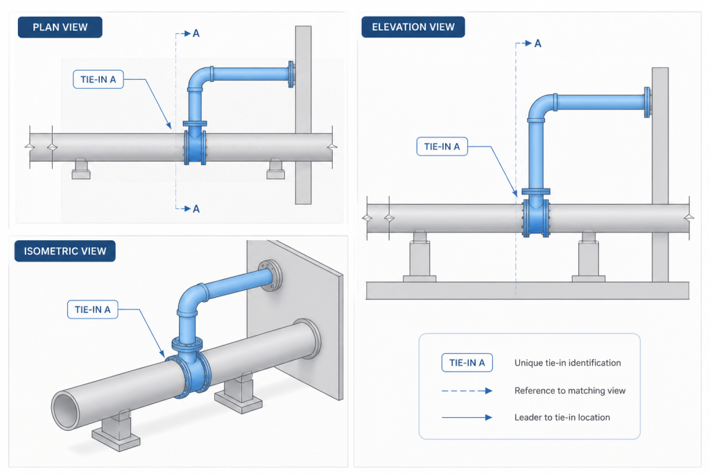
Each drawing type answers a different coordination question:
- Plan view: Where is the tie-in relative to equipment, structures, access routes, and adjacent piping?
- Elevation or section: At what vertical position does the connection occur, and are supports or clearances affected?
- Isometric: How does the new piping connect, and which components belong to the modification?
- Spool or fabrication drawing: Which portions are shop-fabricated, field-installed, or left for field measurement?
- Tie-in schedule: What interface, line, location, work boundary, and verification information must be tracked?
The same tie-in identifier should refer to the same physical interface in every applicable view. Check that the line number, size designation, component orientation, elevation reference, and connection description agree. A mismatch between a plan and an isometric is often more serious than a drafting inconsistency because it can change the interpretation of the field work.
Review the tie-in before issuing the drawing
A focused tie-in review can be performed independently of the broader model review. Check the following items:
- Is the interface physically identifiable in the drawing?
- Are existing, new, removed, and reference items visually distinct?
- Does the tie-in tag appear consistently on all required views and schedules?
- Is the connection associated with the correct line or equipment item?
- Are field-verified dimensions and conditions clearly marked?
- Is the proposed work boundary clear to design, construction, and operations reviewers?
- Are nearby valves, supports, instruments, access areas, and structural constraints shown where they affect the work?
- Do plan, elevation, section, isometric, and spool information agree?
- Are demolition limits and temporary conditions separated from the permanent design?
- Can the drawing be understood when printed without relying on color?
Why tie-in clarity matters in CAD
A good tie-in detail reduces the gap between the model and the field. It helps reviewers understand the modification, helps planners define the work package, and gives construction personnel a clear interface to verify. It also protects the drawing from a common error: presenting an assumed existing condition as though it were a surveyed fact.
For reliable results, treat every tie-in as a managed interface rather than a simple endpoint. Identify the existing system, show the proposed connection, mark uncertainty, coordinate the surrounding geometry, and carry one consistent identifier through the drawing set. That approach makes piping modifications easier to review, fabricate, install, and update when field conditions differ from the record drawings.
Practical relationships around a tie-in point
A tie-in rarely stands alone in a project document set. Its meaning is developed by comparing the CAD geometry with the line list, equipment information, P&IDs, survey or scan data, field notes, specifications, and construction planning documents that govern the modification. These sources may serve different purposes, so the drawing should make clear which information is graphical context, which information defines scope, and which condition still requires verification.
Connect the drawing to the source record
Before finalizing a tie-in, confirm that the referenced existing line or equipment item is traceable to an identifiable project source. Review the applicable drawing revision, model area, field record, or survey reference and record unresolved conflicts rather than silently choosing one condition. This is especially important when an older drawing shows a different routing, component arrangement, or connection location than the current field information.
Make the work boundary understandable
A connection point, demolition limit, field weld, spool break, and installation boundary can all occur near one another while representing different responsibilities. Use separate symbols, notes, leaders, or schedule entries when these boundaries are not identical. A reviewer should be able to determine what remains in service, what is removed, what is supplied as new work, and what must be confirmed before fabrication or installation.
Review interfaces beyond the pipe centerline
Tie-in coordination should include the nearby conditions that can prevent the work from being installed or operated as intended. Depending on the project, this may include valves, supports, instruments, insulation, access paths, structural members, removable components, drains, vents, temporary supports, and isolation points. Showing relevant context does not mean assigning operations or safety decisions to the CAD drawing; those requirements should remain controlled by the responsible project documents.
Use revision control as part of tie-in control
When field information changes, update the tie-in identifier, affected views, notes, schedules, and related work-package references together. Avoid correcting only the most visible view. A coordinated revision helps prevent a plan, isometric, spool drawing, or field package from carrying an obsolete interpretation of the same interface.
Common tie-in documentation mistakes
- Placing a tie-in leader on a nearby line instead of the actual connection.
- Using a demolition symbol without identifying the retained existing boundary.
- Showing assumed existing geometry with the same visual treatment as verified information.
- Allowing a tag to change between the plan, isometric, schedule, and field package.
- Leaving the connection method implied when the project documents require a defined interface.
- Showing the new route without enough surrounding context to distinguish parallel or adjacent systems.
- Relying on color alone to separate existing, new, removed, and reference geometry.
The most reliable drawings make uncertainty visible and assign the next verification action. That is more useful than adding detail that appears precise but is not supported by the available record.
Frequently asked questions
What is a piping tie-in point in CAD?
It is the documented interface where proposed piping or a modification connects to an existing line, equipment nozzle, utility header, boundary connection, or other installed system. It should identify the physical interface and the related work and verification limits.
Is a field weld the same as a tie-in point?
No. A field weld describes a construction or installation division, while a tie-in identifies the existing-to-new interface. They may be located together, but the drawing should show their meanings separately when they are not identical.
How should uncertain existing conditions be shown?
Use the project-approved notation for field verification and place it near the affected geometry. The note should make its scope clear and should be connected to a measurement, hold point, survey, or other required confirmation when the uncertainty affects fabrication or installation.
Where should the tie-in tag appear?
Place the tag at the interface with a clear leader when necessary. Repeat the same identifier in every applicable plan, elevation, section, isometric, spool drawing, schedule, or work package so the physical connection remains traceable.
Why should CAD drawings distinguish reference geometry from new piping?
Background geometry provides orientation, but it can be mistaken for construction scope if it is not clearly identified. Distinct layers, line descriptions, notes, legends, and tags help prevent reference information from being interpreted as proposed work.