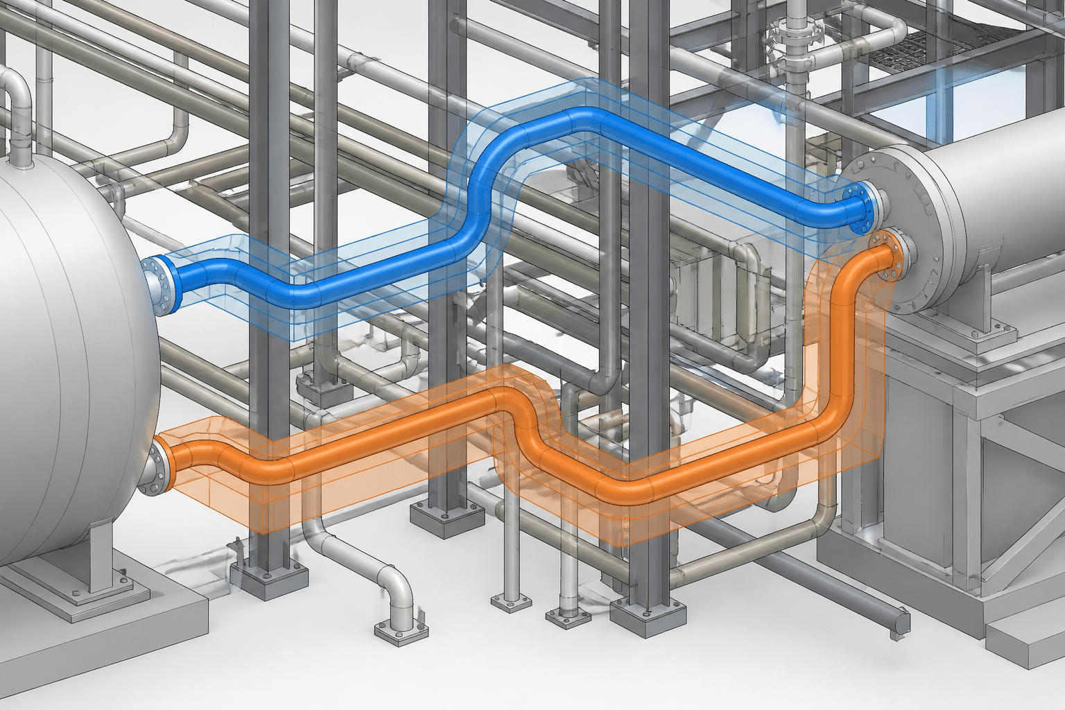
Piping routing studies in CAD help project teams make spatial and coordination decisions before a preferred route becomes expensive to revise. The value of the study is not limited to finding a path between connection points. It is a structured way to compare access, support interfaces, constructability, maintenance space, and coordination risk using consistent assumptions.
A useful routing study also protects design intent. Clear status controls, labeled alternatives, documented assumptions, and decision records help prevent preliminary geometry from being mistaken for approved design. The guidance below explains how to organize that process so the CAD model supports review rather than obscuring it.
A piping routing study is more than drawing several possible paths between two connection points. It is a controlled design exercise used to compare space, access, constructability, support requirements, and future maintenance before a route becomes difficult to change.
When routing options are explored directly in CAD, the model can quickly become crowded with abandoned lines, temporary geometry, and unclear assumptions. A disciplined workflow keeps alternatives understandable and makes the selected route easier to review, coordinate, and document.
What a piping routing study is intended to accomplish
A routing study tests how a line or group of lines can pass through a defined area while respecting known project requirements. The study may be performed in a 2D plan, a 3D model, or a combination of plans, elevations, and sections.
The objective is not necessarily to produce a final fabrication-ready route. Instead, the study should provide enough information to make a reasoned decision and identify issues that require input from other disciplines.
Typical questions include:
- Can the route connect the required equipment, headers, valves, and instruments?
- Does the proposed path preserve access for operation, inspection, maintenance, and removal?
- Will the pipe conflict with structures, equipment, cable trays, ducts, drains, or other piping?
- Can the route be supported using practical attachment points and load paths?
- Does the arrangement allow construction, welding, painting, insulation, testing, and future modification?
- Are slope, drainage, venting, flexibility, or thermal movement requirements affected by the route?
Start with a routing study brief
Before creating alternative geometry, define the information that controls the study. A short routing brief is often more useful than a collection of informal CAD notes because it gives reviewers a common basis for comparison.
The brief should identify the line or system being studied, its known connection points, the area limits, the current model or drawing status, and the decisions that are still open. It should also distinguish confirmed information from assumptions.
Useful categories include:
- Fixed points: equipment nozzles, existing tie-ins, battery limits, structural penetrations, and other locations that should not move without authorization.
- Controlled zones: areas reserved for access, lifting, removable equipment, electrical equipment, instruments, or other services.
- Routing constraints: required slope, known clearance criteria, restricted areas, support limitations, or preferred routing corridors.
- Open inputs: unresolved nozzle orientation, pending equipment dimensions, uncertain structural steel, or incomplete insulation information.
- Review objective: the specific decision the study must support, such as selecting a pipe rack corridor or comparing an overhead route with a low-level route.
This brief prevents the CAD operator from treating every visible object as equally authoritative. A background model may contain preliminary equipment, reference steel, or geometry that has not yet been approved.
Separate fixed, flexible, and reference geometry
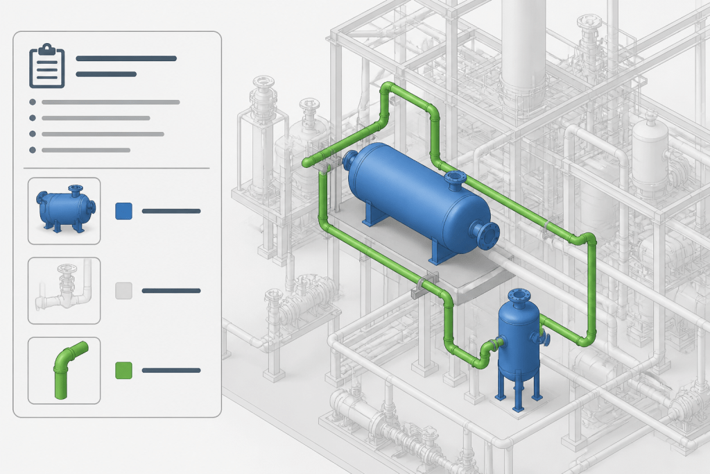
Alternative routing is easier to manage when geometry is separated by purpose. Use a clear layer, workset, color, or model status system for each category permitted by the project CAD standard.
Fixed geometry represents items that control the study, such as equipment, structural boundaries, and confirmed connection points. Study geometry represents the route being evaluated. Reference geometry shows nearby systems or objects used for coordination but not modified during the study.
Abandoned alternatives should not remain visually indistinguishable from the selected route. They can be placed on separate layers or saved as separate model options, then hidden for the main review view. Do not simply delete every rejected route if the decision history may be needed; retain it in an appropriately controlled study file or archive.
Build alternatives from the same starting assumptions
A fair comparison requires consistent inputs. If one route is modeled with insulation and another is modeled as bare pipe, their apparent clearances will not be comparable. The same applies to valve envelopes, removable spool zones, access areas, support interfaces, and equipment maintenance spaces.
For each alternative, use the same:
- Connection points and endpoint definitions
- Pipe size, material, and specification information available at the study stage
- Insulation or external treatment assumptions
- Valve and instrument envelope assumptions
- Reference model revision
- Required drawing scale and level of detail
If an assumption differs between options, record the difference explicitly. Otherwise, the review may focus on a visual advantage that disappears when the design is developed further.
Compare routes using practical criteria
Visual appearance alone is a weak basis for selecting a piping route. A route that looks short may create difficult support conditions, poor access, excessive field work, or an unfavorable drain point. Use a comparison matrix to make the tradeoffs visible.
| Review criterion | Questions to ask | CAD evidence |
|---|---|---|
| Connectivity | Does the route reach every required endpoint without hidden breaks or uncertain connections? | Continuous centerline, endpoint markers, and checked connections |
| Space and clearance | Does the route fit within the available corridor and preserve required access zones? | Plans, sections, and clearance envelopes |
| Supportability | Can supports connect to practical steel, concrete, equipment, or dedicated support structures? | Indicative support locations and attachment interfaces |
| Constructability | Can the line be fabricated, transported, installed, welded, tested, and insulated? | Break points, access areas, and installation sequence notes |
| Operations and maintenance | Can operators reach controls and can maintainers remove components? | Access zones, removal paths, and equipment envelopes |
| Future flexibility | Does the route leave room for known expansion, tie-ins, or replacement? | Reserved corridors and clearly marked future interfaces |
The matrix does not replace engineering calculations or discipline reviews. It organizes the spatial evidence so that the team can identify which alternative creates fewer downstream problems.
Use the right views for each review question
A single isometric view rarely proves that a route works. Use several views, each selected for a particular verification task.
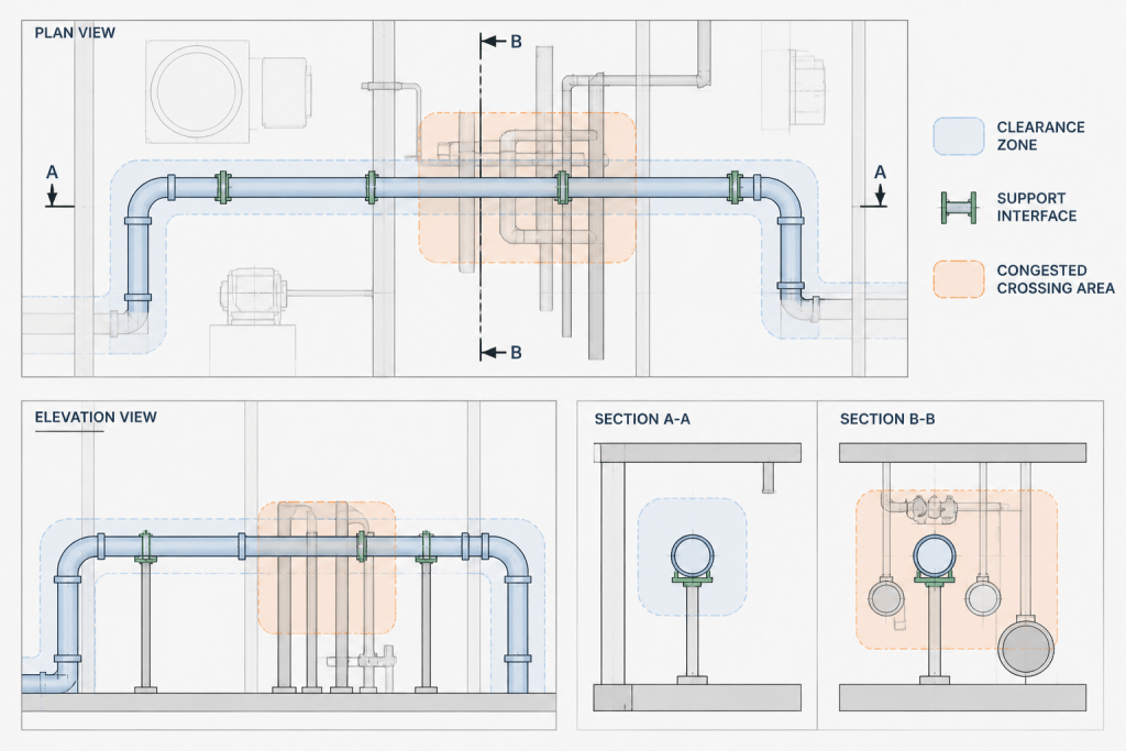
- Plan view: compare corridors, horizontal offsets, equipment relationships, and conflicts with nearby services.
- Elevation view: inspect vertical separation, slope direction, support levels, and crossings.
- Section view: verify tight areas where plan and elevation information overlap.
- Isometric view: communicate overall connectivity, component orientation, and the relationship between route segments.
- Enlarged detail: examine congested connections, access zones, penetrations, and support interfaces.
When a view is used to support a decision, label the alternative and identify the relevant area. Reviewers should not have to guess whether a line is the current option, an earlier option, or background reference geometry.
Record the reason for selecting a route
The selected route should have a short decision record. This is especially important when the preferred option is not the shortest or visually simplest path.
Record the selected alternative, the date or review stage, the responsible discipline or team, the main reasons for selection, and the unresolved actions. Include rejected alternatives when their rejection explains an important constraint, such as poor access or lack of support locations.
Use objective language. “Selected because it avoids the maintenance removal path and provides practical support locations” is more useful than “best option.” If the decision depends on an unconfirmed input, state that condition clearly and assign an action to verify it.
Carry the selected route into the controlled model
After approval, do not redraw the route manually in several documents. Promote the selected geometry through the project workflow so that plans, elevations, isometrics, material data, and coordination views use the same design basis.
Before the route leaves study status, check the following:
- Temporary alternative geometry is hidden, archived, or clearly marked as superseded.
- Endpoints match the current equipment and piping data.
- Route ownership and status are clear to other disciplines.
- Required valves, instruments, drains, vents, and branch connections are included or listed as open items.
- Support, flexibility, insulation, and access reviews are assigned where the study did not resolve them.
- Drawing notes and model metadata no longer describe the route as preliminary if it has been approved for the next stage.
Common routing study mistakes
- Comparing incomplete alternatives: One route includes maintenance envelopes while another shows only centerlines.
- Leaving rejected routes visible: Reviewers mistake old geometry for the selected design.
- Ignoring vertical information: A route appears clear in plan but conflicts in elevation.
- Routing without support thinking: The pipe fits spatially but has no practical attachment strategy.
- Over-detailing too early: Time is spent refining components before the corridor decision is stable.
- Failing to record assumptions: Later users cannot tell which inputs were confirmed and which were provisional.
A well-managed piping routing study gives the project more than a preferred line path. It creates a traceable design decision, exposes coordination risks early, and provides a controlled starting point for detailed CAD production. The best study is not the one with the most geometry; it is the one that makes the route decision clear and keeps its design intent intact as the project develops.
Why routing studies work best as controlled comparisons
A CAD model can show where a pipe fits, but it does not automatically explain whether the route is practical to build, support, operate, inspect, or modify. Those questions require the route to be reviewed in relation to surrounding systems and project constraints.
The most reliable comparison keeps the design basis consistent while changing only the routing alternative under review. That means using the same connection definitions, surrounding model status, equipment and component envelopes, and known access requirements wherever they apply. When an input is uncertain, the uncertainty should be visible rather than silently resolved by the CAD operator.
Connect the study to the wider design workflow
A routing study sits between early layout development and more controlled design production. It can expose issues for piping, mechanical, structural, electrical, instrumentation, construction, operations, and maintenance reviewers. It should therefore make open questions easy to assign and track.
- Layout coordination: show how the proposed route interacts with equipment, structures, services, and restricted areas.
- Support development: identify whether the route has credible attachment interfaces and a practical load path for later engineering.
- Access planning: preserve space for operation, inspection, component removal, and construction activities.
- Model control: distinguish approved, provisional, reference, and superseded geometry.
- Design communication: use views and notes that let reviewers understand the decision without reconstructing the model history.
What a strong study deliverable contains
The deliverable does not need to contain every detail of a finished piping model. It should contain enough evidence for the intended decision. Depending on the review, that may include alternative route views, endpoint markers, clearance or access envelopes, indicative support interfaces, open-item notes, and a concise selection record.
This approach keeps the model proportionate to the question being asked. Corridor selection may require clear spatial relationships and access zones, while a congested connection may require enlarged sections and more explicit component envelopes. In both cases, the study should state what has been checked and what remains subject to discipline review.
Preserve design intent after selection
Approval of a route is not the end of the information-management task. The selected alternative should be promoted through the controlled project workflow without being manually re-created in disconnected drawings or models. Status, ownership, assumptions, and unresolved actions should remain understandable to the next person who develops or reviews the design.
When rejected alternatives are retained, they should be clearly separated from active geometry and stored according to the project document-control process. This preserves useful decision history without allowing obsolete lines to create coordination errors.
Frequently asked questions
What is the main purpose of a piping routing study in CAD?
Its purpose is to compare possible routes against project requirements such as connectivity, space, access, supportability, constructability, maintenance, and future interfaces before the route is developed further.
Should rejected piping routes be deleted?
Not necessarily. Rejected alternatives may provide useful decision history, especially when they document a constraint such as poor access or inadequate support locations. They should be archived, hidden, or marked as superseded so they cannot be mistaken for the active route.
Why should every routing alternative use the same assumptions?
Consistent assumptions make the comparison meaningful. Differences in insulation treatment, component envelopes, access areas, reference model status, or level of detail can make one route appear better for reasons unrelated to its actual layout.
Which CAD views are useful for reviewing a piping route?
Plans help compare corridors and horizontal relationships. Elevations show vertical separation, slope direction, and support levels. Sections clarify congested areas, while isometric and enlarged detail views communicate connectivity, orientation, access, and interfaces.
Does a routing study replace detailed engineering review?
No. It organizes spatial evidence and highlights issues for follow-up. Support design, flexibility, insulation, access, constructability, and other discipline reviews may still be required before the route is released for later design stages.
What should be recorded when a route is selected?
Record the selected alternative, review status, responsible team, principal reasons for selection, unresolved actions, and any decision that depends on an unconfirmed input. Objective reasons are more useful than a general statement that one option is the best.