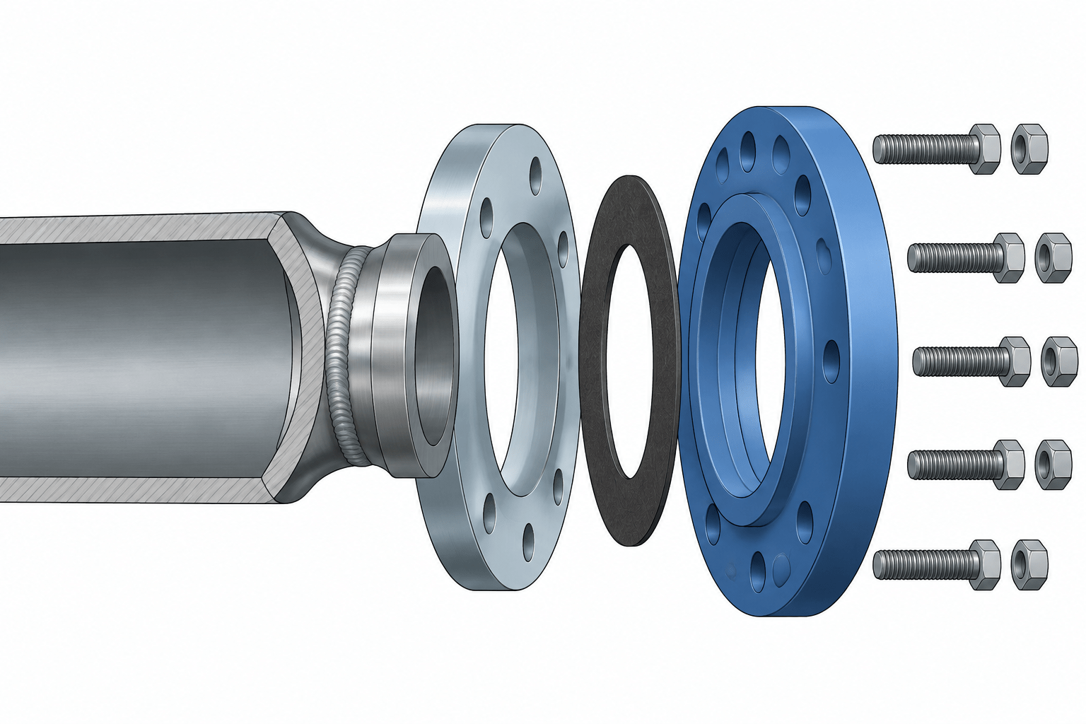
Lap joint flange and stub end CAD modeling requires more than selecting a flange-shaped object from a component library. The connection is an assembly in which the attached stub end establishes the sealing and fabrication references, while the loose backing flange supplies the bolting interface and remains rotatable during alignment.
This guide explains how to preserve those separate functions in component geometry, connection ports, spool dimensions, isometrics, and material reports. It is intended as a practical review aid; final component selection and joint suitability must be checked against the governing piping specification and verified manufacturer or project data.
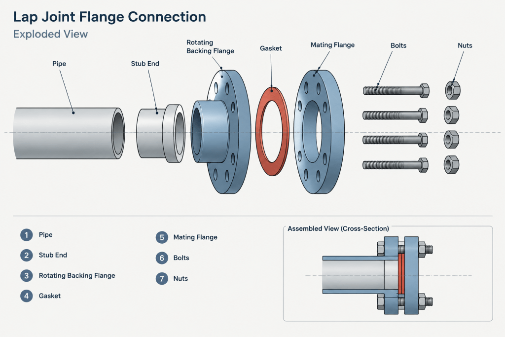
A lap joint flange connection is not represented accurately by treating the flange as a conventional one-piece flanged end. The joint normally combines two separate components: a stub end that is attached to the pipe and a loose backing flange that bears against the stub end. Each component has a different function, and that distinction affects CAD geometry, dimensions, material takeoffs, flange rotation, and fabrication drawings.
This arrangement can be useful where bolt-hole alignment or material selection makes a rotating flange desirable. However, the freedom to rotate the backing flange should not be confused with freedom to move the sealing surface or change the assembled length. The stub end remains part of the pressure-containing pipe assembly and controls the location of the gasket contact surface.
How the assembly works
The stub end is joined to the pipe, commonly by a circumferential butt weld when the selected component and piping specification call for that construction. Its flared end forms the lap against which the loose flange bears. The backing flange slides over the pipe or stub-end barrel before final assembly and transfers bolt load to the lap.
Unlike a weld neck or slip-on flange, the backing flange is not normally welded directly to the pipe in this arrangement. It can rotate around the pipe axis before bolt-up. That rotation helps the bolt holes align with the mating flange, but the flange is still restrained axially by the stub-end lap when the joint is assembled.
| Assembly part | Primary function | CAD significance |
|---|---|---|
| Stub end | Provides the pipe attachment and gasket contact area | Controls the weld location, joint face, and axial geometry |
| Backing flange | Provides the bolting ring and bears against the lap | Controls bolt pattern representation and requires rotational freedom |
| Gasket | Seals between compatible joint faces | Occupies the interface between the opposing sealing surfaces |
| Bolting | Clamps the complete joint | Depends on the full joint stack-up, not the flange ring alone |
The stub end controls the connection face
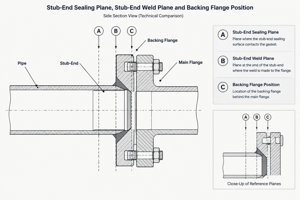
For layout purposes, the critical connection plane is the sealing face of the stub end, not the front surface of the loose backing flange. A model that places the connection port on the backing flange may produce incorrect spool lengths, gasket positions, or mating-component locations.
The stub end also establishes the distance from its sealing face to its weld end. That distance must come from the governing component data selected for the project. Similar-looking stub ends may not be dimensionally interchangeable, and a generic CAD symbol should not be used as evidence of actual fit.
When setting component ports or insertion points, a practical model separates the following references:
- the pipe centerline;
- the stub-end weld plane;
- the stub-end sealing plane;
- the backing flange center plane or other library reference;
- the mating flange face; and
- the gasket location.
This separation makes it easier to check face-to-face geometry without relying on the displayed thickness or outline of the backing flange.
Rotation is useful, but it must be modeled correctly
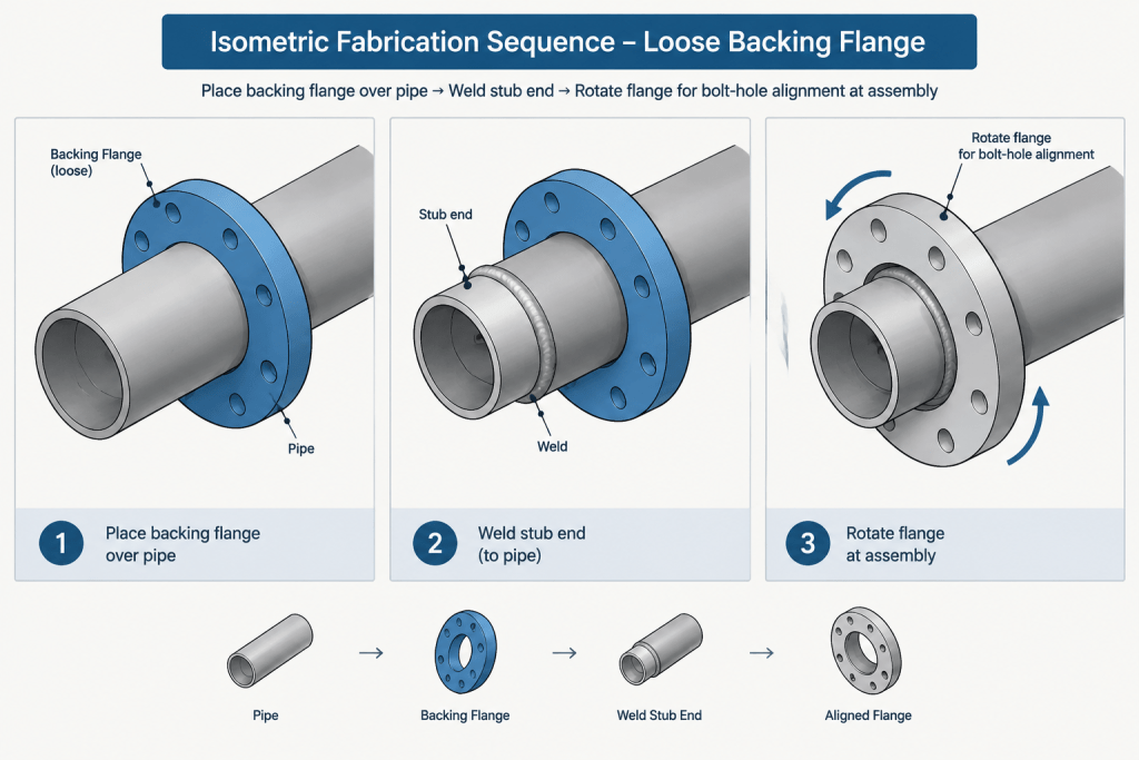
The loose flange can generally be rotated before the bolts are installed. In a CAD assembly, the bolt-hole pattern should therefore remain independently rotatable around the pipe centerline until its orientation is coordinated with the mating flange.
A common modeling mistake is to lock the backing flange rotation to the stub end or pipe as though all three were a single welded component. This removes one of the assembly’s important practical features. The opposite mistake is allowing the flange to slide axially without limit. Rotation may be available, but axial placement is still governed by the stub-end lap and the assembled joint.
On drawings where bolt-hole orientation is important, show the final coordinated orientation of the backing flange. Do not imply that the stub end itself must rotate after welding. If the drawing uses a bolt-hole clocking convention, apply it consistently and verify the mating equipment or flange requirement.
Dimensioning the spool
Spool dimensions should be based on functional fabrication references. The stub-end weld plane is relevant to pipe cut length, while its sealing face is relevant to the final connection location. The backing flange thickness alone does not define either value.
For a spool with a stub end at one or both ends, check the dimensional chain in this order:
- Establish the required final sealing-face location.
- Apply the verified stub-end face-to-weld dimension.
- Locate the circumferential weld plane.
- Calculate the pipe cut length using the selected fitting takeouts and weld preparation assumptions.
- Confirm that the backing flange is placed over the pipe before any fabrication step that would trap it outside the assembly.
- Check the assembled gasket and mating-face relationship.
That installation sequence matters. A correctly dimensioned spool can still be unusable if fabrication prevents the loose flange from being installed in its intended position.
Material and specification considerations
One reason for separating the components in the model and bill of materials is that the stub end and backing flange may not have the same material description. In some services, the pressure-contacting stub end is selected for process compatibility while the loose backing flange is selected under a different material requirement. This is project- and specification-dependent, not an automatic rule.
The model should carry independent properties for each item, including component type, nominal size, material, applicable dimensional basis, and any project-specific description. Do not copy the backing flange material onto the stub end merely because the two are inserted as one CAD assembly.
Compatibility also requires more than matching nominal size. The designer should verify the selected stub end, backing flange, mating flange, gasket, bolting, facing arrangement, and piping specification as a complete joint. CAD geometry can expose obvious conflicts, but it does not establish pressure suitability or code compliance.
BOM and isometric treatment
The stub end and lap joint flange should normally remain identifiable as separate components in the material takeoff. Combining them under a vague description such as “flange set” can hide differences in quantity, material, procurement, or fabrication responsibility.
An isometric may show the pair with a compact symbol, but the bill of materials should clearly distinguish the parts. The weld joining the stub end to the pipe should also be represented according to the project’s weld identification method. The loose flange itself should not be depicted as welded to the pipe unless the actual design includes a separately specified feature that requires it.
Recommended CAD object structure
- Create a stub-end object with ports at the weld end and sealing face.
- Create a separate backing-flange object with a defined axial location and rotatable bolt pattern.
- Associate both objects as an assembly without merging their material properties.
- Place the gasket between the actual sealing faces.
- Allow reports to count the stub end, flange, gasket, and bolting separately.
Common drafting and modeling errors
- Using the backing flange face as the piping endpoint: This can shift the mating component or alter spool length.
- Modeling the assembly as a weld neck flange: The connection geometry and fabrication sequence are different.
- Omitting the stub end from the BOM: The pressure-containing attachment can disappear from procurement data.
- Locking bolt-hole rotation too early: This removes the adjustment available during fit-up.
- Ignoring flange installation sequence: The loose flange may become trapped on the wrong side of another component.
- Assuming visual fit proves compatibility: Similar CAD outlines do not confirm facing, material, pressure-temperature capability, or dimensional compliance.
Final review checklist
- Is the piping connection plane located at the stub-end sealing face?
- Is the stub-end weld plane based on verified component data?
- Can the backing flange rotate to match the mating bolt pattern?
- Is axial movement constrained by the physical assembly?
- Are the stub end and backing flange listed separately in the BOM?
- Are their material descriptions independently assigned?
- Is the gasket shown between compatible sealing surfaces?
- Has the fabrication sequence been checked so the loose flange can be installed?
- Have the mating flange, bolting, and complete joint stack-up been verified?
A reliable lap joint flange model preserves the functional difference between the welded stub end and the rotating backing flange. When the connection face, weld plane, rotation, materials, and BOM structure are handled separately, drawings become easier to fabricate, coordinate, and review.
Applying the model through the drawing workflow
The same assembly logic should remain consistent from the piping model through orthographic drawings, isometrics, fabrication details, and material reports. A simplified drawing symbol may be acceptable for presentation, but simplification should not relocate the functional connection plane or merge separate procurement items.
Design-model review
Review the stub end as the component attached to the pipe and the backing flange as a related movable part. Confirm that the connection port, weld reference, gasket interface, and bolt-pattern orientation are controlled by the correct objects. The visible flange outline should not override these functional references.
Drawing extraction review
Check whether extracted dimensions reference the intended sealing or weld plane rather than an arbitrary object origin. If a drawing shows bolt-hole orientation, its graphics should agree with the coordinated assembly state. Hidden or simplified geometry should not make the loose flange appear welded to the pipe.
Data and reporting review
Component grouping can help users select and move the assembly, but grouping should not erase individual identities. Each reportable item should retain its own description and specification properties so procurement and fabrication teams can distinguish the stub end, backing flange, gasket, and bolting.
Change-management review
When a stub end or flange definition is replaced, recheck the connection plane, weld plane, flange position, bolt-hole orientation, gasket interface, and material records. A replacement that looks correct on screen may still change an insertion point, reporting category, or dimensional reference. Geometry and data should therefore be reviewed together.
Frequently asked questions
Which part defines the piping connection point?
The connection point should follow the stub-end sealing surface because that is where the mating joint face and gasket interface are established. The front of the loose backing flange is not a substitute for that functional plane.
Should the stub end and backing flange be one CAD object?
They may be associated as an assembly for selection and placement, but their geometry, movement, material properties, and reporting identities should remain distinguishable. Merging them can conceal fabrication and procurement differences.
What movement should the backing flange have?
The model should represent rotation around the pipe axis for bolt-hole coordination while preventing unrealistic axial movement in the assembled condition. Its final position must reflect how it bears against the stub-end lap.
Does a visually aligned CAD joint confirm compatibility?
No. Visual alignment can identify obvious interference or orientation problems, but it does not verify facing compatibility, materials, bolting, gasket selection, pressure-temperature suitability, or compliance with the project specification.
What should be rechecked after replacing a library component?
Recheck object origins, connection ports, weld and sealing planes, flange orientation, gasket placement, assembly constraints, and bill-of-material properties. Component replacement should not be accepted solely because the displayed shape appears similar.