Tag: instrumentation

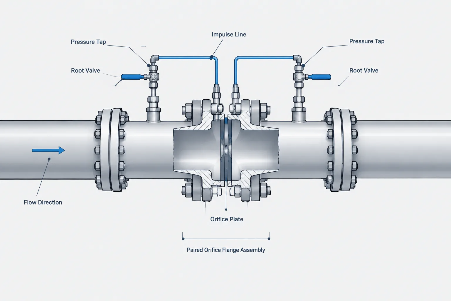
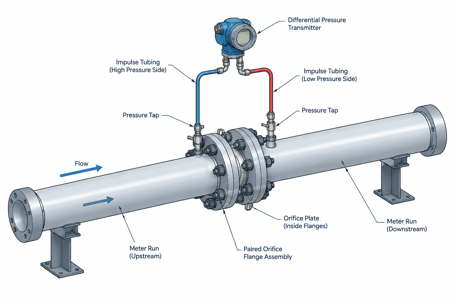
  • Orifice Flanges in Piping CAD: Pressure Taps, Plate Orientation, and Meter-Run Control

    Orifice Flanges in Piping CAD: Pressure Taps, Plate Orientation, and Meter-Run Control

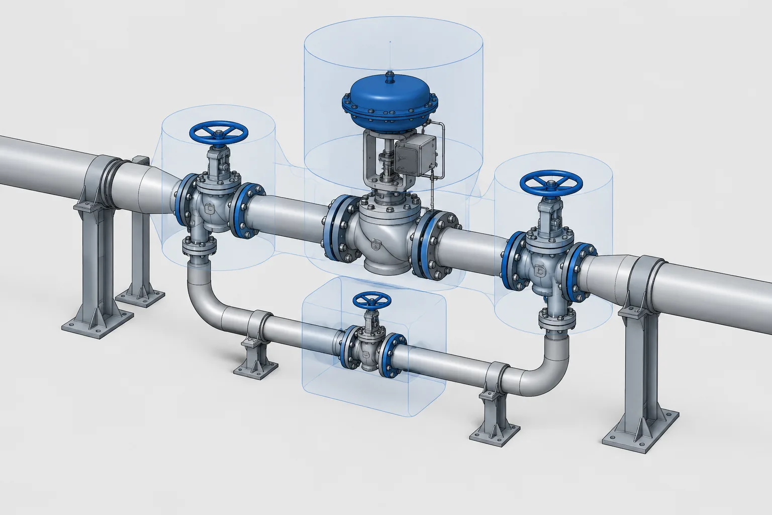
  • Control Valve Station Layout in Piping CAD: Bypass, Isolation, Access, and Removal

    Control Valve Station Layout in Piping CAD: Bypass, Isolation, Access, and Removal

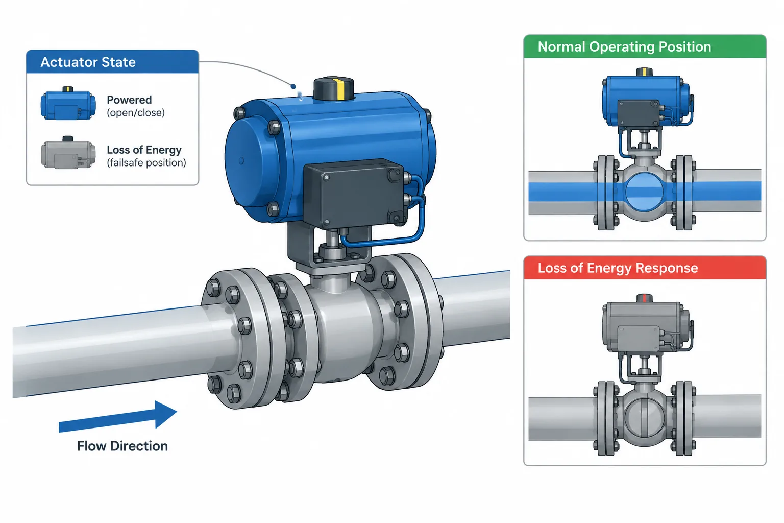
  • Valve Normal Position vs. Fail Position: How to Read and Document Operating States

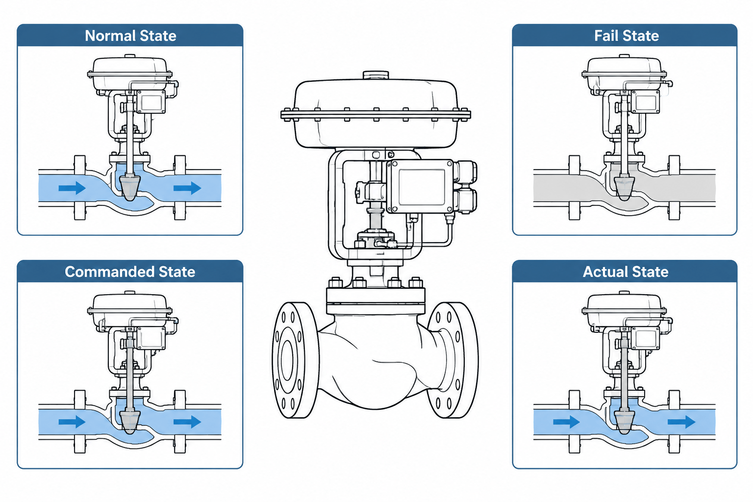
    Valve Normal Position vs. Fail Position: How to Read and Document Operating States

  • Orifice Flanges and Meter Runs in Piping CAD: A Practical Layout and Detailing Guide

    Orifice Flanges and Meter Runs in Piping CAD: A Practical Layout and Detailing Guide

  • Valve Position Terminology in P&IDs and CAD: Normal, Fail, and Commanded States

    Valve Position Terminology in P&IDs and CAD: Normal, Fail, and Commanded States

  • How to Detail Instrument Connections and Small-Bore Piping in CAD

    How to Detail Instrument Connections and Small-Bore Piping in CAD

  • P&ID Symbols | Piping and Instrumentation Diagram

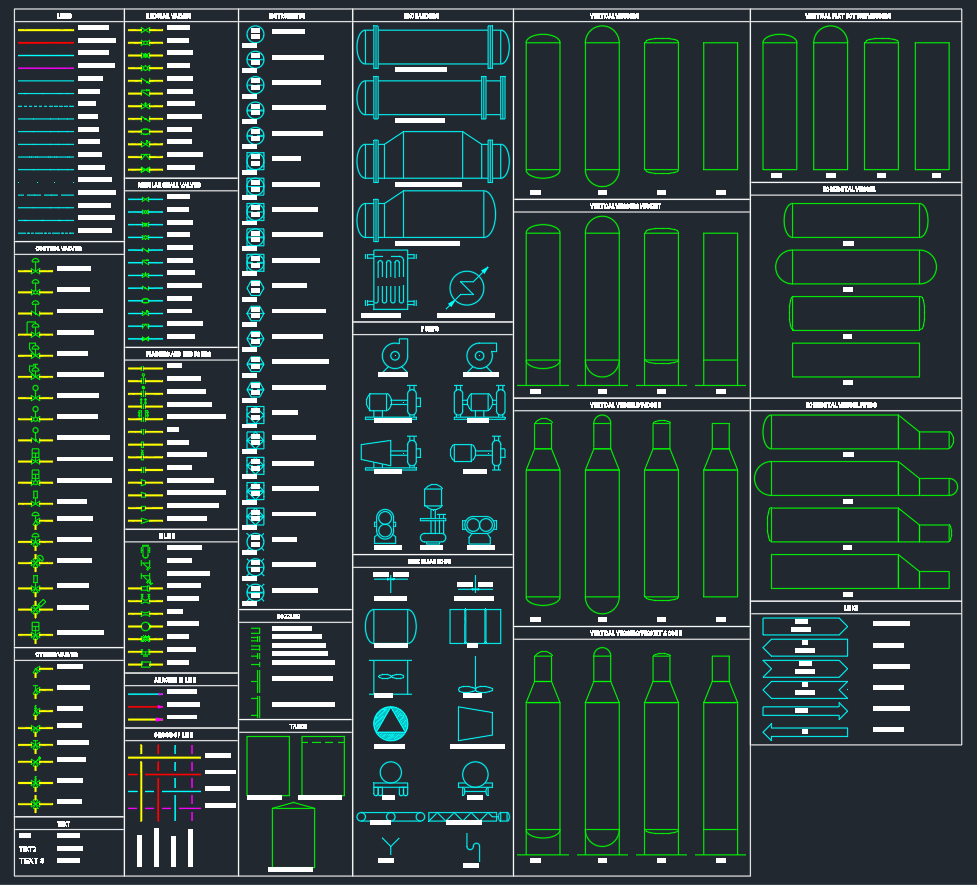
    P&ID Symbols | Piping and Instrumentation Diagram

  • P&ID of Nitrogen Generation Plant (PSA Nā‚‚ Plant)

    P&ID of Nitrogen Generation Plant (PSA Nā‚‚ Plant)

  • P&ID Symbols | DWG Library for Process & Instrumentation Diagrams

    P&ID Symbols | DWG Library for Process & Instrumentation Diagrams