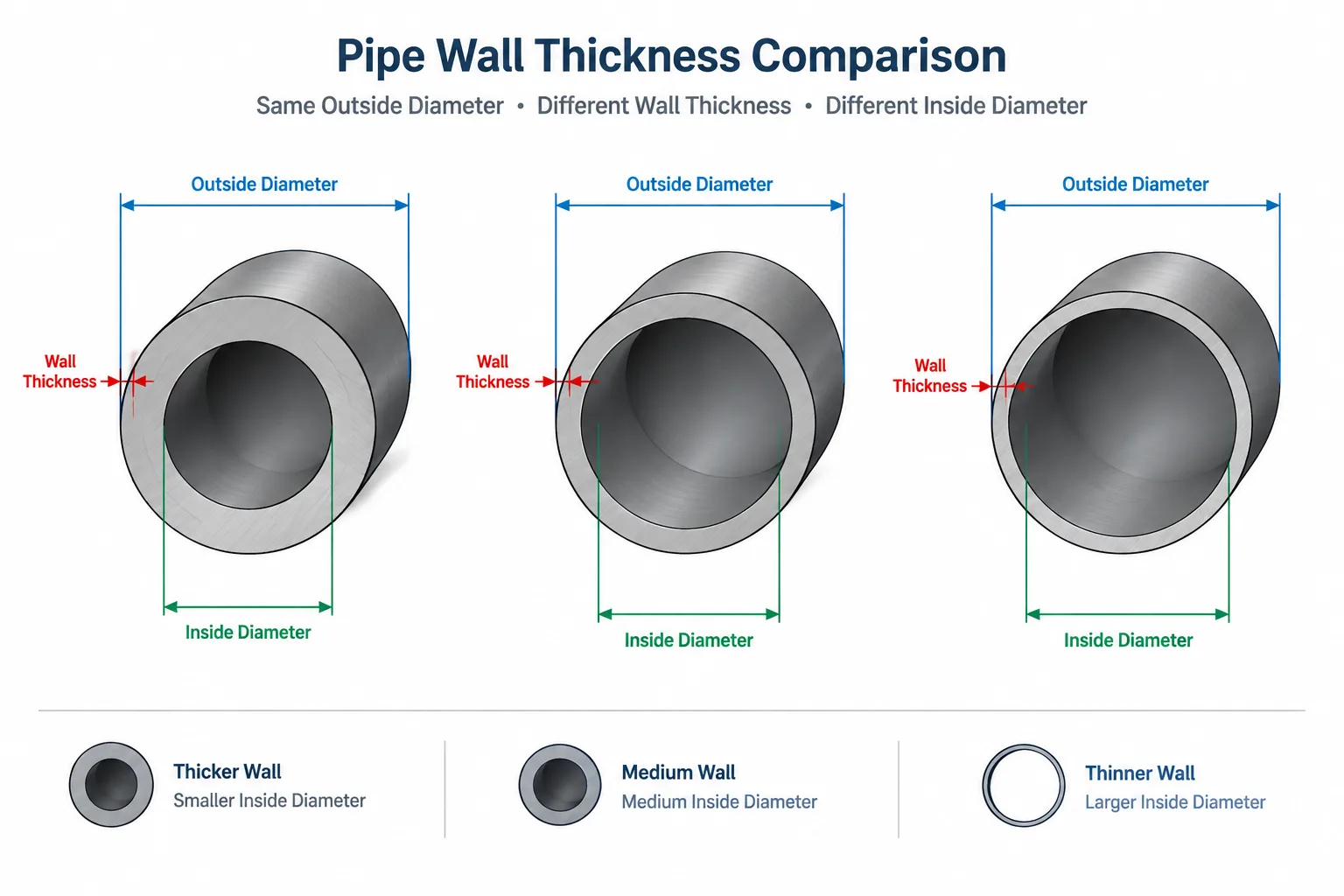
Pipe inside diameter and flow area cannot be determined from nominal pipe size alone. Nominal size identifies a compatible piping family, while the available bore depends on the selected outside diameter, wall thickness, lining, and any restrictions within connected components.
This guide explains how those properties relate, why schedule changes matter, and how to carry reliable bore data through hydraulic calculations, piping specifications, CAD models, and design reviews.
Nominal pipe size is a convenient way to identify compatible pipe, fittings, flanges, and valves, but it does not directly state the open area available for flow. Two pipes with the same nominal size can have the same outside diameter while using different wall thicknesses. Their inside diameters—and therefore their internal flow areas—will differ.
This distinction matters when moving between piping specifications, dimensional references, hydraulic calculations, equipment connections, and CAD models. A line may be labeled correctly by nominal size while still carrying the wrong bore information for pressure-drop calculations, velocity checks, fabrication planning, or internal-clearance review.
Nominal size, outside diameter, and inside diameter
Three related terms must be kept separate:
- Nominal pipe size: A standardized size designation used to organize piping components. It is not generally a direct measurement of the bore.
- Outside diameter: The external diameter of the pipe body. For most commonly used nominal pipe sizes, the specified outside diameter remains associated with the nominal size even when the schedule changes.
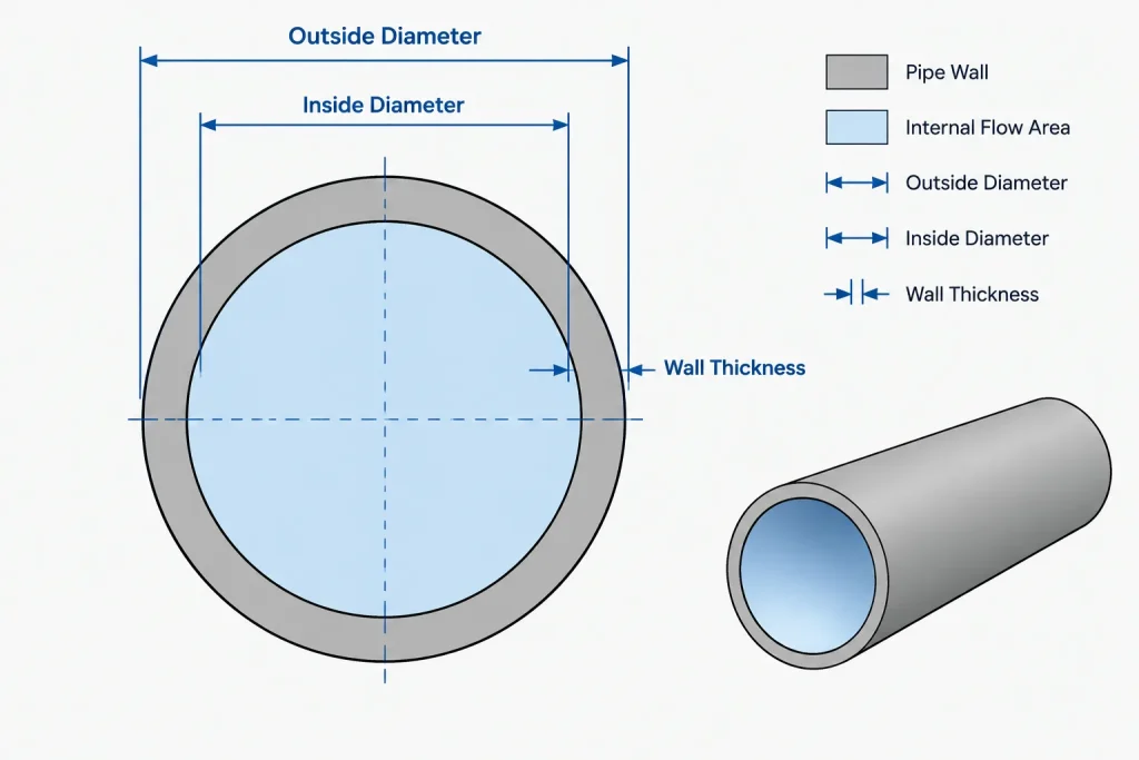
- Inside diameter: The approximate clear diameter within the pipe, based on outside diameter and wall thickness.
For a simple pipe section with a uniform circular wall, the basic geometric relationship is:
Inside diameter = outside diameter − twice the wall thickness
This equation is straightforward, but selecting the correct input values is not always straightforward. The wall must come from verified dimensional information for the specified pipe size and schedule or stated wall thickness. A schedule label alone is not a universal thickness value, and the same schedule designation does not imply one constant wall thickness across all nominal sizes.
How inside diameter determines flow area
Once the calculation diameter has been established, the cross-sectional area of a circular bore can be calculated as:
Flow area = π × inside diameter² ÷ 4
Because diameter is squared, a modest change in inside diameter can produce a more noticeable change in area. This is why substituting a heavier wall pipe without updating hydraulic data can affect calculated velocity and pressure loss even though the nominal line size and external CAD geometry appear unchanged.
For a given volumetric flow rate, a smaller internal area produces a higher average velocity. That change may also affect calculated friction loss and other system-specific checks. The engineering significance depends on the fluid, service, piping configuration, calculation method, and applicable design criteria.
Why pipe schedule matters
Pipe schedule is a wall-thickness identification system. It is often displayed beside nominal size in line lists, specifications, bills of material, and component properties. It should not be interpreted as the bore or as a direct pressure rating.
When the nominal size remains the same and wall thickness increases, the usual geometric result is:
- The pipe outside diameter remains unchanged.
- The inside diameter becomes smaller.
- The metal cross-sectional area becomes larger.
- The internal flow area becomes smaller.
This creates an important CAD limitation. A centerline model or a model showing only outside geometry may not reveal that the selected schedule has changed. The component can look identical in an overall layout while carrying a different internal diameter in its data.
Terms that should not be treated as interchangeable
| Term | What it describes | Typical use |
|---|---|---|
| Nominal size | A standardized component size designation | Line identification and component compatibility |
| Outside diameter | The external pipe diameter | Clearance, supports, insulation, and connection geometry |
| Wall thickness | The radial thickness of the pipe wall | Dimension selection and engineering checks |
| Calculated inside diameter | Outside diameter minus twice the selected wall thickness | Basic bore and area calculations |
| Nominal bore | A general size description that may not equal measured internal diameter | Terminology and system classification |
| Effective flow area | The usable area after considering relevant internal restrictions | Detailed hydraulic or process evaluation |
Calculated bore versus effective bore
The inside diameter calculated from pipe outside diameter and wall thickness describes the straight pipe body under an idealized circular-wall assumption. It does not automatically describe the minimum opening throughout an assembled piping system.
Potential restrictions include:
- Valve seats, discs, balls, gates, and internal body passages
- Reducer transitions and reduced-port components
- Branch fitting intersections
- Gaskets projecting into the bore
- Weld penetration or internal misalignment
- Internal linings, coatings, sleeves, or inserts
- Strainer screens and other flow elements
- Deposits, fouling, or accumulated solids in operating systems
A full-port valve description also should not be converted into an assumed internal dimension without checking verified manufacturer information. Product terminology can indicate a design category, but the actual passage geometry belongs to the selected component.
Linings and internal barriers
A lined pipe can retain the same external steel geometry while having a smaller usable bore. If the lining thickness is relevant to a hydraulic or clearance calculation, the calculation basis should explicitly identify whether the diameter represents the base pipe bore or the finished lined bore.
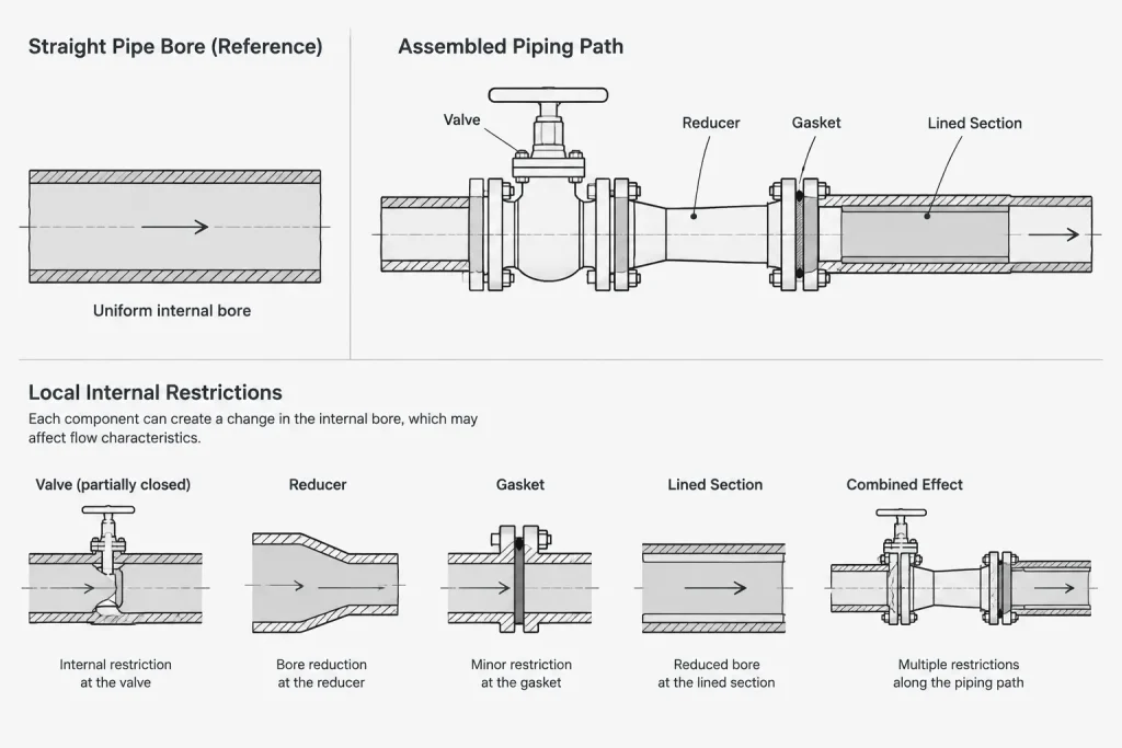
The same principle applies to cementitious linings, polymer liners, corrosion-resistant internal layers, and inserted sleeves. Their finished dimensions may depend on the piping specification and manufacturing details. A CAD model should not invent a uniform lining thickness merely to make the model appear complete.
Internal diameter can also matter for instruments, cleaning devices, inspection tools, and inserted equipment. In these cases, checking only the straight-pipe bore is insufficient. The entire travel path may need review for local restrictions, bends, valve passages, branches, and dimensional transitions.
Do not confuse nominal dimensions with manufacturing limits
The simple inside-diameter equation normally uses nominal or specified dimensional values. Real pipe can vary within applicable manufacturing tolerances, and its cross section may not be perfectly circular. The resulting minimum or maximum internal dimension may therefore differ from the nominal calculated bore.
The correct treatment depends on why the diameter is needed. A preliminary flow estimate, a detailed hydraulic model, and a mechanical clearance study may require different dimensional assumptions. The calculation record should state whether it uses nominal wall, a specified wall, a tolerance-adjusted wall, or verified measured dimensions.
Corrosion allowance also requires careful interpretation. It is an engineering input associated with material loss over the design basis; it is not automatically an instruction to subtract an arbitrary amount from the published inside diameter. The dimensional and hydraulic conventions should come from the project’s engineering method rather than an undocumented CAD assumption.
A practical bore-data workflow
1. Confirm the line identity
Start with the line number, nominal size, material or piping class, and service. Do not select a bore using nominal size alone.
2. Identify the wall basis
Determine whether the line is controlled by a pipe schedule, a directly specified wall thickness, or another dimensional system. Verify that the designation applies to the selected material and component type.
3. Retrieve verified dimensions
Use the project-approved dimensional source or verified reference data to obtain outside diameter and wall thickness. Avoid measuring a schematic symbol, generic block, or rendered model.
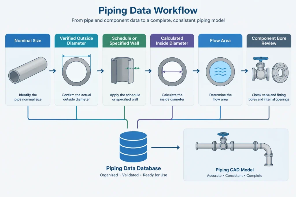
4. Calculate the straight-pipe bore
Apply the diameter relationship consistently and retain enough precision for the intended calculation. Do not round the diameter prematurely when it will be squared to calculate area.
5. Review local restrictions
Check valves, fittings, liners, gaskets, instruments, and specialty items if the task depends on minimum passage or effective area.
6. Record the calculation basis
State whether the result uses nominal dimensions, finished lined dimensions, manufacturer data, measured field data, or another defined basis. This makes later review possible when the piping class or component selection changes.
Managing inside diameter in CAD and data systems
A piping model benefits from keeping size designation, outside diameter, wall thickness, and calculated inside diameter as separate properties. Combining them into a single text description makes automated checking and schedule changes more difficult.
Useful model or database fields may include:
- Nominal size designation
- Outside diameter
- Schedule or specified wall
- Nominal wall thickness
- Calculated pipe inside diameter
- Lining or internal-barrier status
- Data source or catalog identifier
- Component bore information where available
Not every drawing needs to display all these fields. The goal is to preserve the data behind the geometry so that reports, hydraulic handoffs, and quality checks can distinguish nominal size from actual dimensional inputs.
Common errors to avoid
- Using nominal pipe size as the inside diameter
- Assuming a schedule number is itself a wall-thickness measurement
- Changing schedule without updating bore-dependent calculations
- Reading an inside diameter by scaling a CAD block
- Assuming every valve or fitting has the same opening as the connected pipe
- Ignoring a lining when finished bore is important
- Mixing nominal, tolerance-adjusted, and measured dimensions without labeling them
- Rounding diameter values before calculating area
The key distinction
Nominal size organizes the piping system, outside diameter controls much of its external geometry, and wall thickness determines the basic pipe bore. Flow area must be derived from the correct inside diameter rather than inferred from the line label or visual model.
Keeping these properties separate allows designers, drafters, and engineers to use the same piping data for different purposes without confusing connection compatibility, physical clearance, and hydraulic performance.
Using bore information across engineering disciplines
Inside diameter data often moves between piping design, process calculations, mechanical specifications, procurement records, and CAD catalogs. Each discipline may use the same nominal line designation for a different purpose, so the dimensional basis should travel with the result.
A useful handoff identifies the nominal size, selected wall basis, source of the outside diameter and wall thickness, calculated or verified bore, and whether linings or component restrictions were considered. Without that context, a technically correct area calculation can be applied to the wrong pipe configuration.
Reviewing changes that can affect flow area
A nominal line size may remain unchanged while its internal geometry changes. Bore-dependent work should therefore be reviewed when a piping class, schedule, specified wall, material system, lining, valve type, reducer arrangement, or specialty component changes.
The review should distinguish between changes that affect external layout and changes that affect the internal passage. A schedule substitution may leave the modeled outside geometry looking unchanged, while a component substitution may introduce a local restriction that is not represented by the straight-pipe inside diameter.
Questions for a design or model review
- Does the calculation use verified outside diameter and wall-thickness data for the selected pipe?
- Is the reported diameter a nominal calculated bore, a finished lined bore, an effective passage, or a measured field value?
- Have valves, fittings, gaskets, instruments, and other local restrictions been considered where relevant?
- Do the hydraulic record, piping specification, line list, and CAD properties describe the same configuration?
- Will a later schedule or component change trigger review of bore-dependent calculations?
These checks help prevent nominal-size compatibility from being mistaken for hydraulic equivalence.
Frequently asked questions
Is nominal pipe size the same as inside diameter?
No. Nominal pipe size is a standardized designation used to organize compatible piping components. The calculated inside diameter depends on the applicable outside diameter and selected wall thickness.
Does changing pipe schedule change flow area?
It can. For the same nominal size and outside diameter, a thicker wall produces a smaller calculated inside diameter and therefore a smaller internal flow area.
Can schedule be used directly as a wall-thickness value?
No. A schedule is a wall-thickness identification system, not a universal thickness measurement. The applicable wall thickness must be obtained from verified dimensional information for the selected nominal size and pipe specification.
Is calculated pipe bore always the effective flow opening?
No. The straight-pipe bore does not account automatically for valve passages, reducer transitions, liners, projecting gaskets, weld conditions, instruments, deposits, or other local restrictions.
Should inside diameter be measured from a CAD model?
Not unless the model contains verified internal geometry created for that purpose. Centerline models, schematic blocks, and outside-envelope models may not represent wall thickness or finished bore.
Why should diameter not be rounded too early?
Flow area is calculated from the square of the inside diameter. Premature rounding can carry into the area result, so calculation precision should be retained until the appropriate reporting stage.