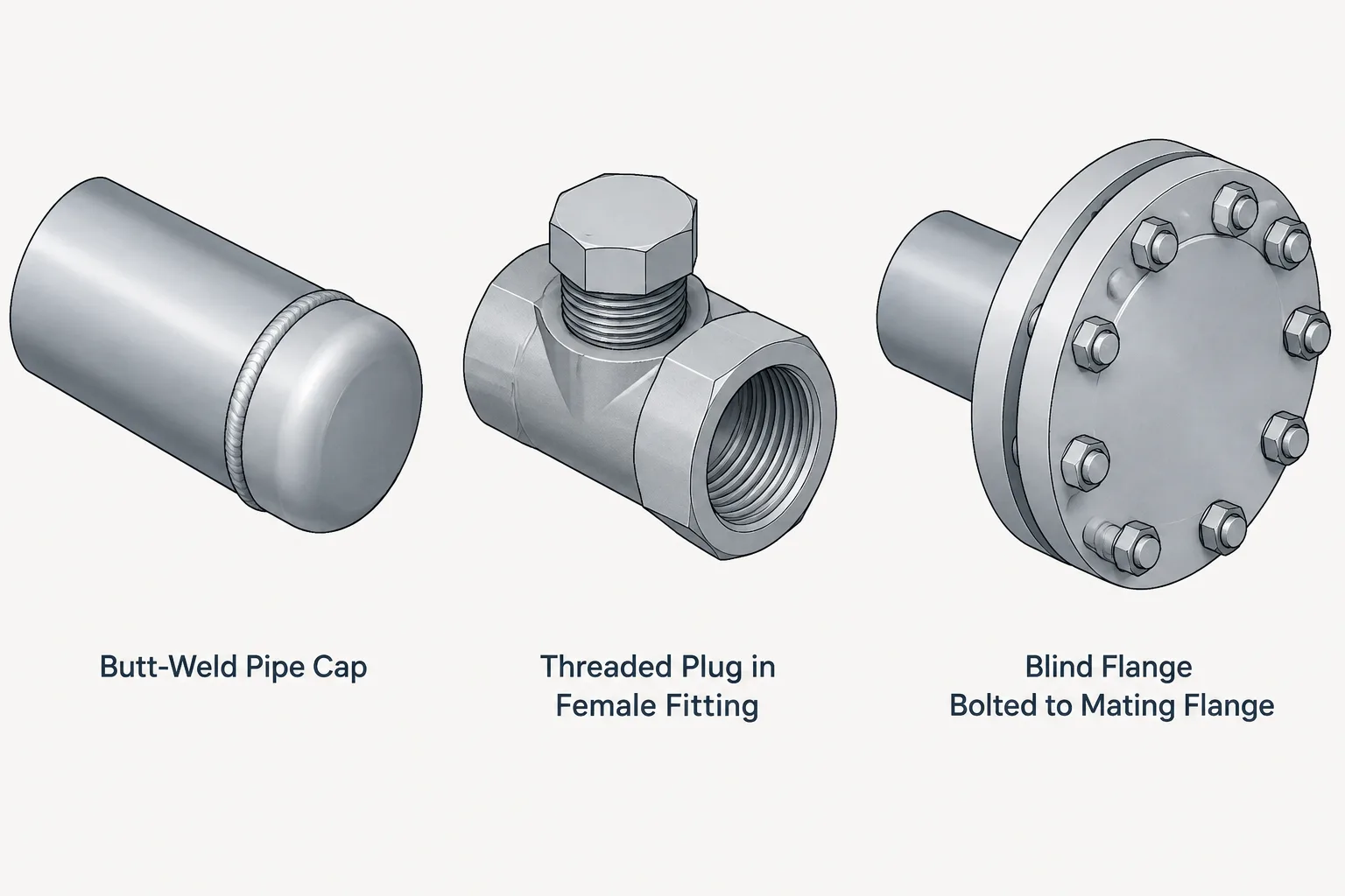
Selecting a piping closure begins with the receiving connection, not merely the need to cover an opening. Pipe caps, plugs, and blind flanges terminate different end arrangements and create distinct requirements for fabrication, sealing, removal, clearance, and material reporting.
This guide explains how to distinguish these closure types and represent them clearly in piping layouts, CAD models, isometrics, and bills of materials. Final selection should follow the approved piping specification, verified component data, service requirements, and project procedures.
Pipe caps, plugs, and blind flanges can all close an opening, but they are not interchangeable components. Each closure uses a different connection method, occupies a different amount of space, and creates different requirements for fabrication, access, inspection, and future removal.
The distinction matters in both design and CAD work. A generic note such as “cap end” may be interpreted as a welded cap, a threaded cap, a plug, or even a bolted blind. That ambiguity can affect the material list, spool length, maintenance plan, and pressure-boundary details. The correct choice begins with the type of opening being closed and the intended function of the closure.
What each closure actually does
Pipe cap
A pipe cap closes the end of a pipe or fitting. The cap generally surrounds or aligns with the end being closed, depending on its connection type. Common configurations include butt-weld, socket-weld, threaded, and other joining systems selected by the piping specification.
A butt-weld cap becomes part of the fabricated pipe assembly. Its open end is prepared for welding to the pipe, while its closed end forms the pressure boundary. A threaded cap normally has internal threads and screws over an externally threaded pipe end or male fitting. These two components share the name “cap,” but their geometry, assembly method, and maintenance implications are very different.
Pipe plug
A plug usually closes a female opening. A threaded plug has external threads and is installed into a threaded fitting, valve body, equipment connection, or branch opening. Plug heads may have different drive or wrenching forms, so the required access depends on the selected component.
Plugs are often associated with small openings such as drains, vents, inspection points, or unused threaded branches. That does not mean every unused opening should automatically receive a plug. The piping specification, service conditions, sealing method, accessibility, and operating procedure still govern the selection.
Blind flange
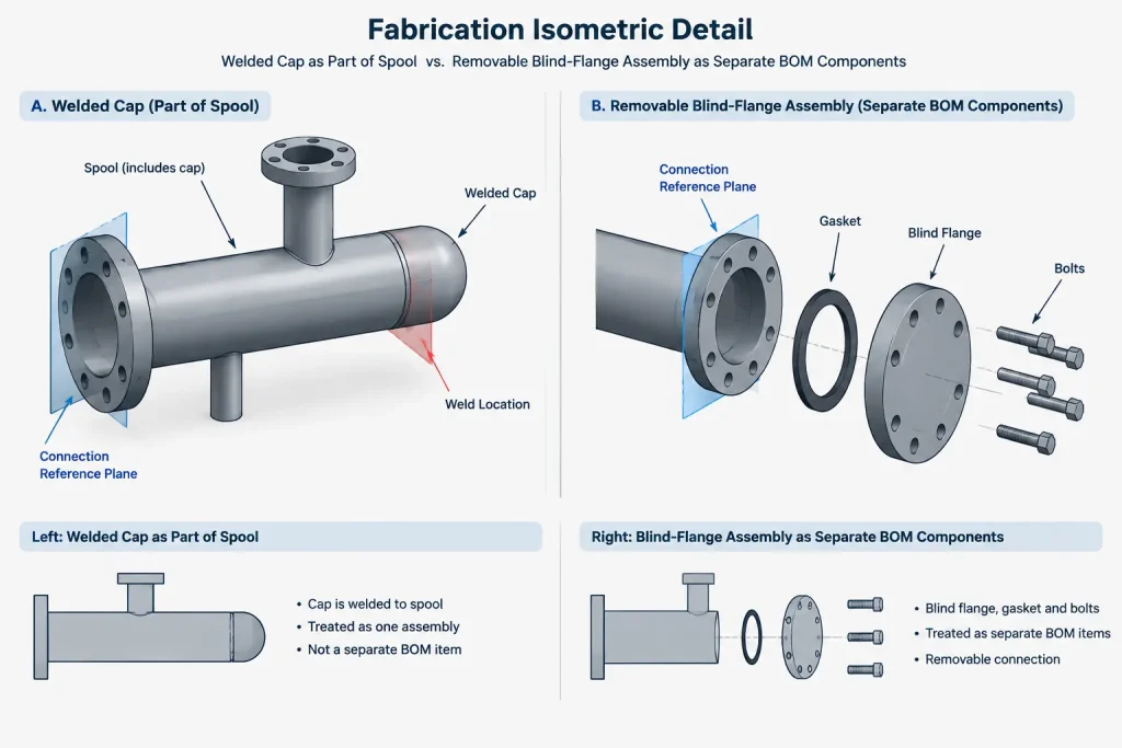
A blind flange closes a flanged connection. Unlike a cap or plug, it is installed as part of a bolted flange joint. The assembly includes the mating flange, gasket, studs or bolts, nuts, and the blind flange itself.
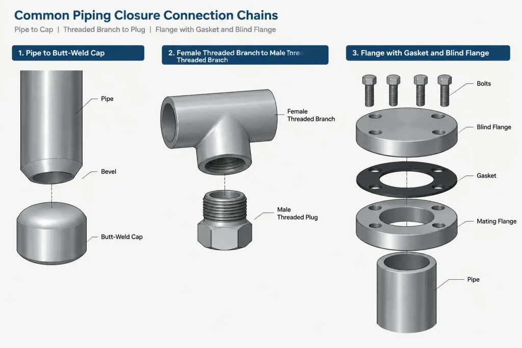
A blind flange provides a removable closure when the bolted joint can be safely accessed and depressurized. It also requires more space than a welded cap because the complete joint envelope includes flange outside diameters, bolting, and tool access. Its use should not be confused with a line blind or spacer installed between flanges for operational isolation; those items have different functions and handling procedures.
Caps, plugs, and blind flanges compared
| Closure | Typical receiving connection | Removal character | Key CAD concern |
|---|---|---|---|
| Butt-weld cap | Butt-weld pipe end | Normally removed by cutting | Cap length, weld location, and spool cut length |
| Threaded cap | Externally threaded end | Thread-removable when accessible | Thread makeup, wrench clearance, and projecting envelope |
| Threaded plug | Internally threaded opening | Thread-removable when accessible | Head style, engagement, and tool access |
| Blind flange | Mating flange | Bolted and removable | Joint stack-up, bolting envelope, gasket, and handling space |
This comparison describes the basic geometry rather than permission for use. The project piping class and applicable design requirements must establish which closure types, materials, ratings, facing details, threads, and joining methods are acceptable.
Start with the receiving end
The connection already present often narrows the choice. A beveled butt-weld pipe end is naturally associated with a compatible welded closure. A female threaded branch may accept a suitable threaded plug. A flanged nozzle requires a matching flanged closure unless the connection is redesigned.
Changing the closure can therefore require more than replacing one catalog item. Substituting a blind flange for a welded cap requires a flange at the pipe end, additional weld and bolting information, a gasket, and more physical space. Replacing a plug with a cap may require changing the male-female thread arrangement or adding another fitting.
Designers should check the entire connection chain rather than treating the closure as an isolated object. In a CAD model or isometric, trace the run from the parent pipe through any branch fitting, nipple, coupling, flange, or adapter to the final closed end.
Permanent closure versus planned access
A welded cap is often selected where a compact fabricated ending is desired and routine access is not expected. Reopening the line generally requires cutting and subsequent fabrication work. The designer should consider whether sufficient straight material and workspace will remain if the end must later be modified.
Threaded plugs and caps can be removable, but theoretical removability is not the same as practical maintainability. Corrosion, coatings, deposited material, restricted wrench access, and nearby steel can make removal difficult. The CAD layout should leave room for the actual tool motion associated with the head or body shape.
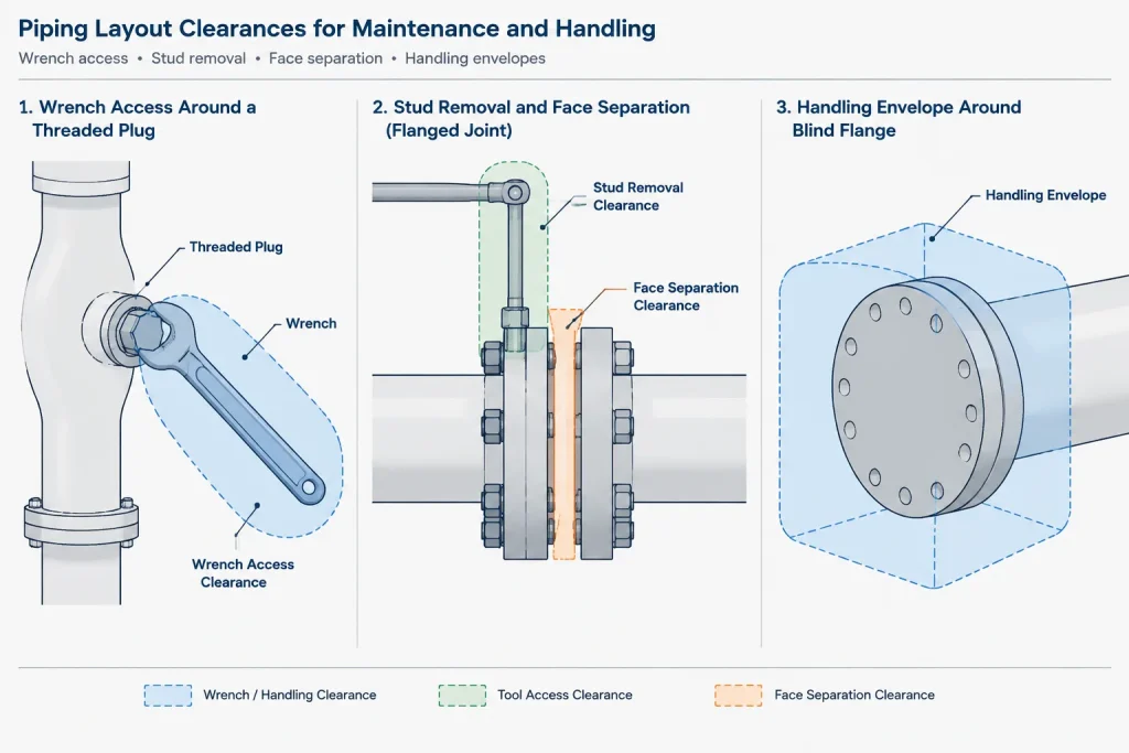
A blind flange is visibly removable and can provide a substantial access opening, but the joint must be dismantled safely. The layout may need room to remove nuts, withdraw studs where applicable, separate the faces, support the blind, and handle the gasket. Larger closures may also require planned lifting or temporary support provisions.
Dimensional control in CAD
Do not model closures as zero-length endpoints
Every closure has a real envelope. A butt-weld cap projects beyond the pipe end. A threaded cap surrounds the threaded end and extends beyond it. A plug head may project outside the receiving fitting. A blind flange adds thickness beyond the mating flange face.
These dimensions can affect wall clearances, drainability, insulation limits, access aisles, equipment removal paths, and overall spool length. Use verified dimensional data for the exact component type and size rather than estimating the closure from the nominal pipe diameter.
Use a meaningful insertion point
A closure CAD component should have an origin that supports reliable placement and replacement. Useful connection references include the weld end plane, threaded connection reference, or flange face. The origin should not be placed at the far end of the visible solid unless that point is also the project’s defined connection reference.
Ports and metadata should identify the connection type. A blind flange should not connect directly to an unflanged pipe endpoint without the required mating flange. Likewise, a plug should not be attached to a male-threaded endpoint merely because the outside diameters appear similar.
Represent the correct joint parts
At low detail, a simplified closure envelope may be enough for routing. Fabrication and material extraction require more information. A flanged closure may need separate records for the blind flange, gasket, and bolting. A threaded closure may require identification of the receiving fitting or nipple. A welded cap needs a weld location and verified end-to-end contribution to the spool.
Orientation and drainage considerations
Caps and blind flanges are generally axisymmetric in simplified models, but the surrounding assembly may not be. A plug with a square, hexagonal, recessed, or projecting drive feature can require a particular tool approach. The CAD representation should show enough of that feature to identify access conflicts when maintenance matters.
A closure at a low point does not automatically create an effective drain. The opening must connect to the portion of the system intended to empty, and the closure must be safely accessible. Similarly, an upward-facing plugged branch may function as a vent or future connection only if its purpose is clearly documented. Geometry alone does not communicate whether a closed branch is active, spare, temporary, or abandoned.
How to document closures on drawings
A useful callout identifies more than the word “cap.” Depending on the document and project convention, the closure record may need to communicate:
- Nominal size and any reducing connection arrangement
- Component type, such as butt-weld cap, threaded plug, or blind flange
- Applicable material or piping class reference
- End connection or flange facing information
- Weld, gasket, and bolting requirements where relevant
- Whether the item is permanent, removable, temporary, or reserved for future use
- Any special access, insulation, coating, or handling consideration
Use terminology consistently across the model, isometric, bill of materials, line list, and maintenance documentation. Calling a threaded plug a cap in one location and a plug elsewhere can create duplicate material descriptions or incorrect purchasing.
A practical CAD review checklist
- Confirm that the closure matches the receiving end connection.
- Verify dimensions from the approved project reference or manufacturer data.
- Check that the model includes the closure’s full external envelope.
- Account for weld, thread makeup, gasket, and bolted-joint stack-up as applicable.
- Provide tool, stud, face-separation, and handling clearance for removable closures.
- Confirm that the closure appears correctly in the material takeoff.
- Identify temporary blinds or test closures separately from permanent components.
- Review nearby insulation, supports, structures, and equipment access zones.
- Ensure the drawing language distinguishes a cap, plug, blind flange, and line blind.
Choosing the right closure
The best closure is not simply the smallest component that covers an opening. It must match the connection, piping class, service intent, fabrication method, and expected need for access. Welded caps offer a compact fabricated termination. Threaded caps and plugs close different thread arrangements and require practical wrench access. Blind flanges create a bolted, removable closure but add joint parts, weight, and clearance demands.
For CAD users, the essential workflow is to model the complete connection, use verified component dimensions, and document why the opening is closed. That approach prevents a visually acceptable endpoint from becoming a fabrication or maintenance problem later.
Apply the selection as a connection decision
A reliable review starts at the open end and works outward. Identify whether the receiving feature is a weld end, male thread, female thread, or flange face. Then confirm that the proposed closure has the corresponding connection and that every required joint component is represented.
This method helps prevent substitutions based only on visual similarity. A cap and plug may appear comparable in a simplified model, but their thread arrangements are opposite. A blind flange may look like a simple plate, yet it belongs to a complete bolted joint rather than directly to an unfinished pipe end.
Coordinate design intent with model detail
The model should communicate whether the closure is a permanent termination, a removable maintenance access point, a spare connection, or a temporary item controlled by a separate procedure. That intent affects component naming, material status, accessibility reviews, and drawing notes.
Early routing models may use simplified geometry, but the connection reference and external envelope should remain meaningful. As the design progresses, the closure record should be coordinated with the piping class, material takeoff, weld information, gasket and bolting records, and maintenance requirements as applicable.
Check the closure during interdisciplinary review
- Piping: Confirm connection compatibility, specification compliance, and complete joint composition.
- Layout: Review the occupied envelope, tool approach, removal path, insulation, and nearby obstructions.
- Fabrication: Verify weld location, spool contribution, thread arrangement, and assembly sequence.
- Operations and maintenance: Confirm that removable closures can be identified, accessed, supported, and handled safely.
- Documentation: Use the same component description and status across drawings, models, lists, and purchasing records.
A closure should be treated as part of the pressure-boundary assembly rather than as a graphical endpoint. Verified project and manufacturer information remains necessary before dimensions, materials, ratings, or joint details are released for fabrication.
Frequently asked questions
What is the basic difference between a pipe cap and a pipe plug?
A cap closes over or joins to a pipe end or male connection, depending on its connection type. A plug generally installs into a female opening. The receiving connection must be identified before choosing between them.
Can a blind flange be installed directly on a pipe end?
A blind flange closes a compatible mating flange as part of a bolted joint. An unflanged pipe end requires the appropriate connection arrangement before a blind flange can be used.
Is a threaded closure always easy to remove?
No. Removal can be affected by corrosion, coatings, deposits, limited wrench clearance, head style, and surrounding structures. CAD reviews should consider actual tool access rather than assuming removability from the thread description alone.
Why should a closure not be modeled as a zero-length endpoint?
Caps, plugs, and blind flanges occupy physical space beyond their connection references. Ignoring that envelope can create conflicts with walls, insulation, supports, equipment, tools, or removal paths.
Is a blind flange the same as a line blind?
No. A blind flange terminates a flanged connection. A line blind is associated with isolation between flanges and has different operational, handling, and documentation requirements.
What should a piping closure callout identify?
The callout should clearly identify the closure type and connection, along with the applicable piping class or material reference and any relevant weld, gasket, bolting, access, or status requirements used by the project.