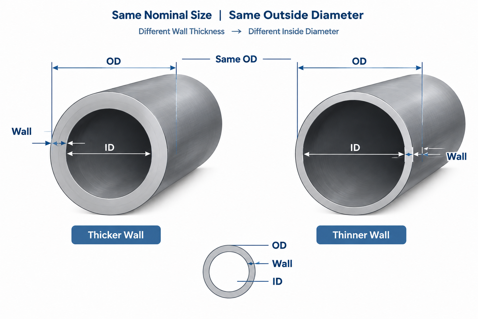
Changing a pipe schedule can alter important engineering data without producing an obvious change in the pipe’s exterior. Within the same nominal size and dimensional series, the outside diameter usually remains fixed while wall thickness changes inward. The resulting difference may be hidden in plan views, elevations, and simplified models.
This guide explains the relationship among nominal size, outside diameter, wall thickness, and inside diameter. It also shows why schedule must be verified through dimensional references, piping specifications, and component data rather than inferred from appearance.
A common source of confusion in piping is the relationship between nominal pipe size, outside diameter, wall thickness, and inside diameter. A pipe may be identified by the same nominal size but offered in several schedules. Across those schedules, the outside diameter normally remains unchanged within the applicable dimensional system, while the wall thickness and inside diameter change.
This arrangement allows fittings, flanges, supports, and other components to interface with a predictable external pipe envelope. It also means that a CAD model can look correct from the outside while containing an incorrect bore or wall specification. Understanding which dimension stays fixed—and which does not—is essential when reading pipe tables, selecting components, preparing isometrics, and checking models.
The Four Terms That Must Be Kept Separate
Nominal pipe size
Nominal pipe size, commonly abbreviated NPS in US practice, is a size designation rather than a direct measurement. It identifies a standardized pipe size family. The nominal value should not automatically be interpreted as either the measured outside diameter or the exact inside diameter.
DN is a related metric designation used internationally. It is also nominal and should not be treated as a simple measured diameter or a direct arithmetic conversion from NPS.
Outside diameter
Outside diameter, or OD, is the measured diameter across the exterior of the pipe. For a given nominal size in the same dimensional series, standard schedule changes generally do not change this outside diameter. The fixed OD provides a common external interface for components that fit around, support, or connect to the pipe.
Wall thickness
Wall thickness is the radial thickness of the pipe wall. Schedule designations are used to identify standardized wall-thickness selections, but the schedule label alone is not a universal thickness value. The actual wall associated with a schedule depends on nominal size and the governing dimensional specification.
Inside diameter
Inside diameter, or ID, is the diameter of the internal flow passage before considering items such as linings, deposits, or manufacturing variation. It is derived from the OD and wall thickness:
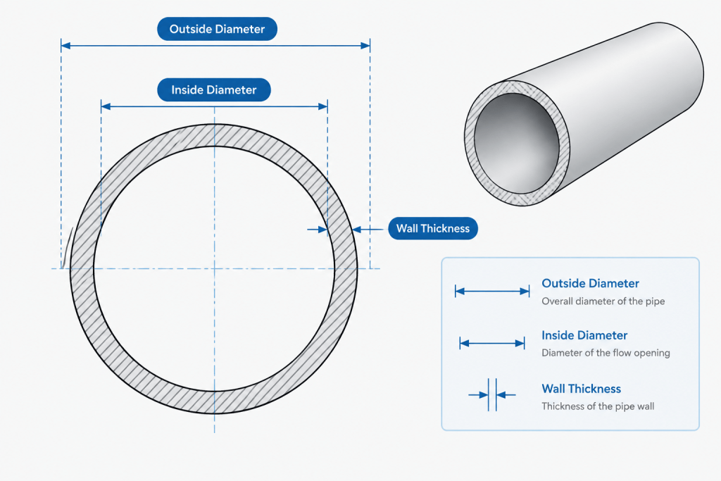
Nominal ID = OD − 2 × nominal wall thickness
The wall is subtracted twice because it occupies space on both sides of a diameter. As the wall becomes thicker while the OD remains fixed, the ID becomes smaller.
What Changes When Schedule Changes?
| Pipe attribute | Typical effect of changing schedule at the same nominal size | Drafting significance |
|---|---|---|
| Nominal size designation | Remains the same | The line may retain the same NPS or DN callout |
| Outside diameter | Normally remains the same within the same dimensional series | The external pipe envelope may appear unchanged |
| Wall thickness | Changes | The specification and material data must be updated |
| Inside diameter | Changes as wall thickness changes | Bore continuity and flow area may be affected |
| Mass per unit length | Generally changes | Support, handling, and material takeoff data may change |
| End and bore details | May require review | Weld preparation, internal transitions, and component bores may differ |
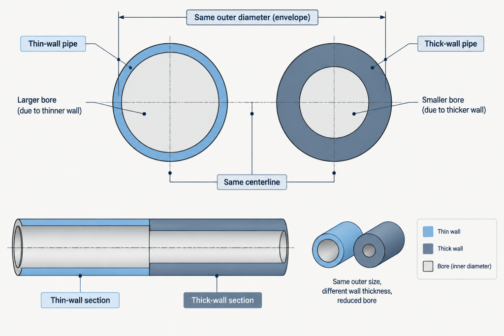
A heavier wall should not be represented by enlarging the outside of standard pipe unless the selected product or specification actually uses a different OD series. In the usual schedule relationship, the added wall extends inward and reduces the bore.
Why a Fixed Outside Diameter Is Useful
Keeping the external diameter consistent supports component interchangeability within a nominal size family. Pipe supports, clamps, guides, seals, and many fitting interfaces depend on the outside surface. If every wall selection produced a different OD, external component selection and plant layout would become substantially more complicated.
A stable OD also helps maintain routing geometry. A pipe centerline can remain in the same location after a schedule change, and its exterior clearance envelope may remain similar. However, this geometric convenience does not make the schedule change insignificant. The revised wall can affect weight, bore, end preparation, welding, branch details, and compatibility with adjoining components.
Why CAD Models Can Hide a Schedule Error
Many piping models represent pipe primarily by centerline and outside diameter. Some workflows store schedule and wall thickness as properties without displaying the internal bore. Others use simplified solids that show only the external cylinder.
As a result, two pipes with the same nominal size but different schedules may look identical in plan, elevation, or shaded 3D views. A visual clash check may pass even though the material assignment is wrong.
A reliable model review should therefore check both geometry and data. Useful fields include:
- Line number or service identifier
- Nominal size
- Pipe material specification or piping class
- Schedule or explicit wall designation
- End preparation where relevant
- Insulation or lining information
- Connected fitting and valve specifications
Do not infer schedule from the modeled OD. For standard pipe of the same nominal size, OD alone may not distinguish one schedule from another.
How Schedule Changes Affect Connected Components
Butt-weld fittings
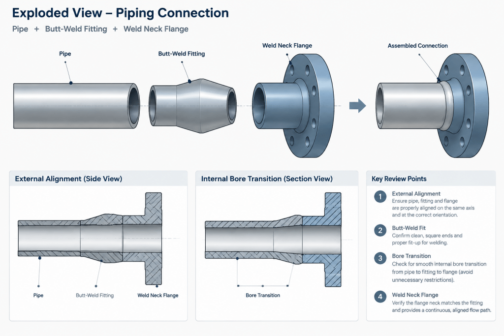
Butt-weld fittings are selected using more than nominal size. Their wall or end configuration must be coordinated with the adjoining pipe and the project specification. If the pipe schedule changes but the fitting data does not, the exterior connection may still align while the internal surfaces or weld ends do not.
The required treatment of a bore mismatch depends on the applicable design rules, fabrication requirements, and approved details. A drafter should identify the mismatch rather than inventing a taper or machining instruction.
Flanges
A flange connection involves separate dimensional concepts. Nominal pipe size identifies the connection size, flange class relates to the flange system, and pipe schedule identifies pipe wall thickness. These terms are not interchangeable.
For weld neck flanges, the bore and welding end deserve particular attention because they interface directly with the pipe wall. A flange that appears correct externally may still have an incompatible bore or end detail.
Socket-weld and threaded components
Socket-weld and threaded components use connection geometries that differ from butt-weld ends. Schedule still matters, but it must be considered with the component rating, bore, engagement, fabrication method, and piping specification. Matching nominal size alone is not a complete compatibility check.
Supports and clearances
Because the bare-pipe OD commonly stays fixed, a standard support envelope may appear unaffected by a schedule change. Nevertheless, increased pipe mass can influence support engineering. Changes to insulation, lining, tracing, or attachments can also alter the real external envelope even when the steel pipe OD is unchanged.
Important Exceptions and Qualifications
“The OD stays the same” is a useful principle, but it must be applied within the correct scope. It assumes comparison of standard schedule selections for the same nominal size and dimensional series. It should not be extended blindly to every tubular product.
- Pipe and tube use different sizing conventions and should not be mixed without verification.
- Special-order pipe, fabricated cylinders, liners, and proprietary systems may not follow ordinary schedule relationships.
- Different material specifications or dimensional standards may use different wall designations or available size ranges.
- Corrosion-resistant linings and internal coatings can reduce the effective flow passage without changing the base pipe OD.
- Manufacturing tolerances mean that nominal values are not guaranteed exact measured dimensions.
- Corrosion allowance is a design input and should not be represented by casually adding material to a catalog wall value.
Always confirm dimensions using the governing project specification and an appropriate verified reference. A schedule label found in a note, vendor file, or legacy drawing should not be accepted without checking its context.
A Practical Pipe Table Reading Workflow
When using a pipe dimension table, follow a controlled sequence rather than scanning for a familiar schedule label:
- Confirm the sizing system. Determine whether the table uses NPS, DN, or another product convention.
- Select the nominal size row. Do not start with the assumed measured diameter.
- Verify the listed OD. Treat it as a physical dimension, not as the nominal size label.
- Find the required schedule or wall column. Confirm that it applies to the selected size and material context.
- Read the wall thickness. Do not assume that the same schedule represents one constant wall across all sizes.
- Determine whether ID is listed or derived. If calculated, identify whether the result is nominal and whether linings or tolerances must be considered separately.
- Check connected components. Review fitting walls, flange bores, valve ends, branch connections, and fabrication notes.
- Carry the data into deliverables. Keep the model, line list, isometric, bill of materials, and purchase description consistent.
Example Without Dimensions
Consider two pipes with the same nominal size and the same standardized OD. Pipe A has a thinner specified wall, while Pipe B has a thicker specified wall. Their centerlines and outside surfaces align when placed in the same CAD location. Pipe B, however, has a smaller internal bore because more material extends inward from the shared outside surface.
If a model displays only exterior geometry, the two pipes may be visually indistinguishable. Their schedule properties, calculated mass, fitting compatibility, and internal transition conditions can still differ. This is why an accurate piping model requires both correct geometry and correct engineering metadata.
CAD and Drawing Review Checklist
- Is the nominal size shown as a designation rather than treated as a measured diameter?
- Was the OD taken from a verified dimensional reference?
- Is schedule or wall thickness consistent with the piping material specification?
- Does the model store wall data even if the bore is not drawn?
- Are butt-weld fitting ends coordinated with the adjoining pipe wall?
- Are weld neck flange bores and ends checked where applicable?
- Have linings, coatings, and corrosion-related requirements been kept distinct from nominal wall?
- Does the bill of materials contain enough information to distinguish pipes that look identical externally?
- Has any schedule change been propagated through connected components and project documents?
Key Takeaway
For standard pipe within the same nominal size and dimensional series, changing schedule normally changes wall thickness inward while the outside diameter remains fixed. The inside diameter therefore changes, even though the pipe may look identical from the outside.
This distinction explains why nominal size, OD, wall thickness, ID, schedule, and flange class must be managed as separate data. In CAD, external geometry alone cannot prove that a pipe is correctly specified. The final check must combine verified dimensions, component compatibility, project specifications, and synchronized model properties.
How to Apply the Fixed-OD Principle
The fixed-OD principle is most useful as a starting point, not as a substitute for checking the governing data. First establish that the compared pipes belong to the same nominal size and dimensional series. Then verify the wall designation and review every component whose bore, end preparation, mass, or fabrication detail depends on that wall.
Separate geometry from specification data
A model’s visible cylinder describes the external envelope, but it may not describe the internal passage or material definition. Treat nominal size, OD, wall thickness, schedule, material specification, lining, and end preparation as separate attributes. A change to one field should trigger a review of related fields rather than an assumption that the existing component selection remains valid.
Use the pipe specification as the control point
When drawings, models, line lists, and bills of materials disagree, the discrepancy should be resolved through the approved project documents and verified dimensional references. Do not choose a schedule merely because it matches an existing graphic or because another line of the same nominal size uses it.
Watch for review warning signs
- A schedule changes in the line list but not in the model properties or bill of materials.
- A pipe replacement is approved based only on matching nominal size and external appearance.
- Connected fittings or weld neck flange details remain unchanged without a bore or end review.
- An internal lining is included in notes but omitted from the effective-passage assessment.
- A support check considers the same OD but overlooks the changed pipe mass or attachments.
- A tube or proprietary piping product is evaluated using ordinary pipe-schedule assumptions.
The practical lesson is that external alignment does not establish full compatibility. A complete review considers the physical dimensions, stored engineering properties, connection details, and controlling project requirements together.
Frequently Asked Questions
Does changing pipe schedule change the outside diameter?
For standard schedule selections within the same nominal size and dimensional series, the OD normally remains unchanged. Different products, sizing conventions, or dimensional series must be checked separately.
Why does inside diameter decrease when wall thickness increases?
When OD remains fixed, added wall material extends toward the center of the pipe. The available internal passage therefore becomes smaller.
Can pipe schedule be identified by measuring OD?
Not by OD alone when the compared pipes share the same nominal size and dimensional series. Wall thickness, product markings, documentation, or another approved identification method is needed.
Is nominal pipe size the same as outside diameter?
No. Nominal pipe size is a standardized designation. It should not automatically be treated as the measured OD or exact ID.
Why can two different schedules look identical in CAD?
Many CAD workflows display centerline and external geometry while storing schedule or wall thickness only as metadata. If the bore is not modeled, schedule differences may not be visually apparent.
Does an unchanged OD mean connected components remain compatible?
No. Fitting walls, flange bores, valve ends, weld preparations, internal transitions, and fabrication requirements may still need review.
Does schedule mean the same wall thickness for every nominal size?
No. A schedule label should not be interpreted as one universal wall value. The applicable wall must be read for the selected nominal size and governing dimensional context.
Do linings change the base pipe OD?
An internal lining can reduce the effective flow passage without changing the base pipe’s external diameter. Its effect should be tracked separately from nominal pipe wall thickness.