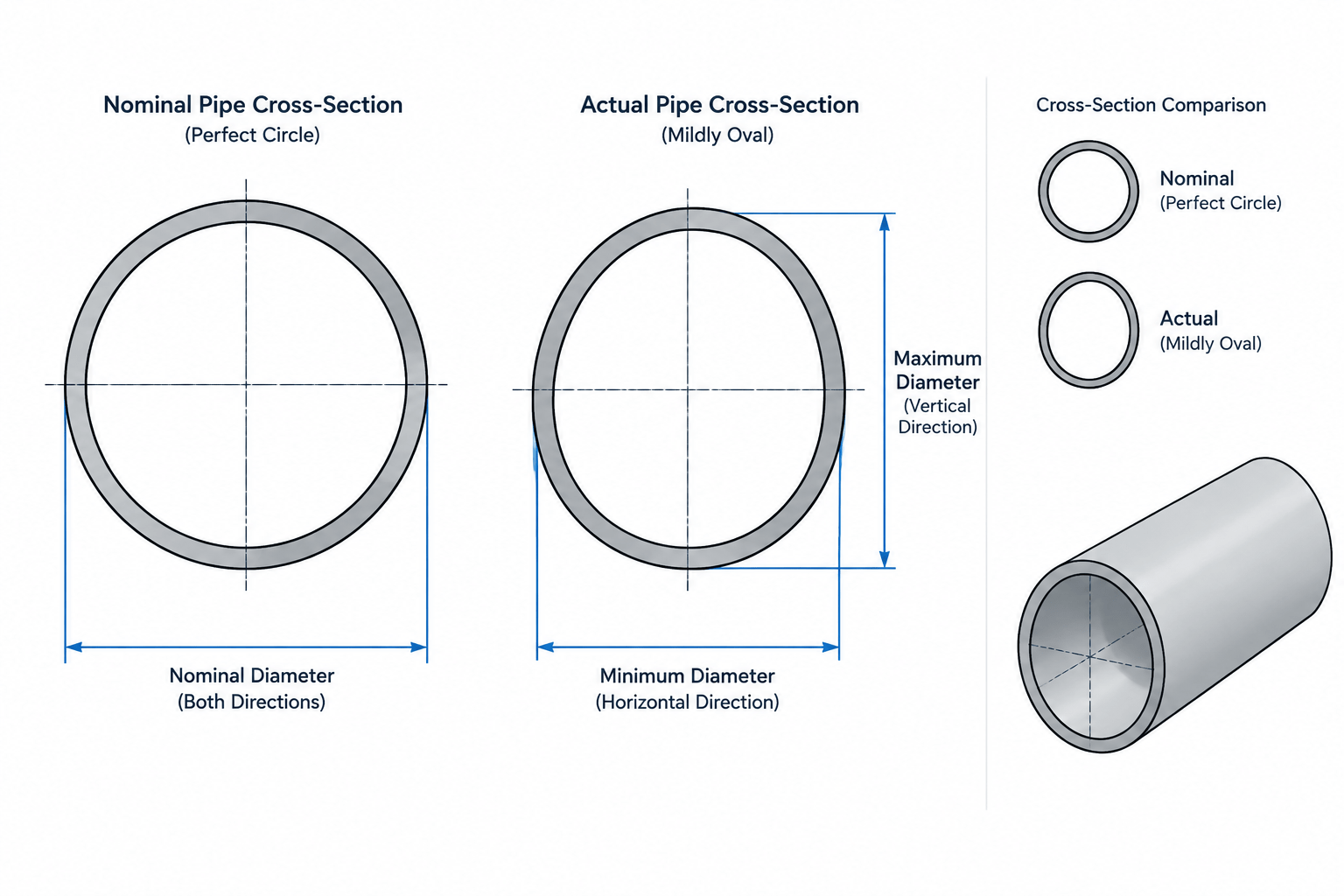
Pipe ovality and out-of-roundness illustrate an important difference between nominal CAD geometry and the physical condition of manufactured or installed piping. A model may be correct for design purposes while still omitting cross-sectional variation that affects fit-up, attachments, clearances, or internal access.
This guide explains when the circular CAD representation is sufficient, when actual pipe geometry should be measured, and how designers can communicate uncertainty without turning an assumed shape into an undocumented field condition.
A piping CAD model normally represents a pipe as a perfectly circular cylinder. That is the correct starting point for most layout, isometric, and material takeoff work, but manufactured or installed pipe is never mathematically perfect. Its cross-section can vary slightly from a true circle because of manufacturing, forming, handling, welding, bending, loading, or installation.
This variation is commonly discussed as pipe ovality or out-of-roundness. The terms are closely related, although their exact calculation and acceptance criteria can depend on the governing material specification, fabrication standard, project specification, inspection procedure, or purchase order. CAD users should therefore understand the physical condition without assuming that a generic geometric formula establishes acceptance.
What pipe ovality means
A truly round pipe has the same outside diameter in every direction through a given cross-section. An out-of-round pipe has a larger measured diameter in one direction and a smaller diameter in another. When this difference produces an elliptical-looking section, it is often described as ovality.
In practice, inspectors commonly compare a maximum measured outside diameter with a minimum measured outside diameter at the same cross-section. A project or product specification may express the result as a direct dimensional difference, a percentage, or another defined measure. Because calculation conventions are not universal, the inspection record should identify the method being used rather than reporting an unexplained “ovality” value.
Out-of-roundness is not the same as using the wrong nominal pipe size or schedule. Nominal pipe size identifies the size family, while schedule or specified wall thickness helps define the wall. Ovality describes variation around an actual cross-section.
Ovality, diameter tolerance, and wall-thickness variation are different
Several dimensional conditions can exist independently, and combining them under one label can lead to incorrect conclusions.
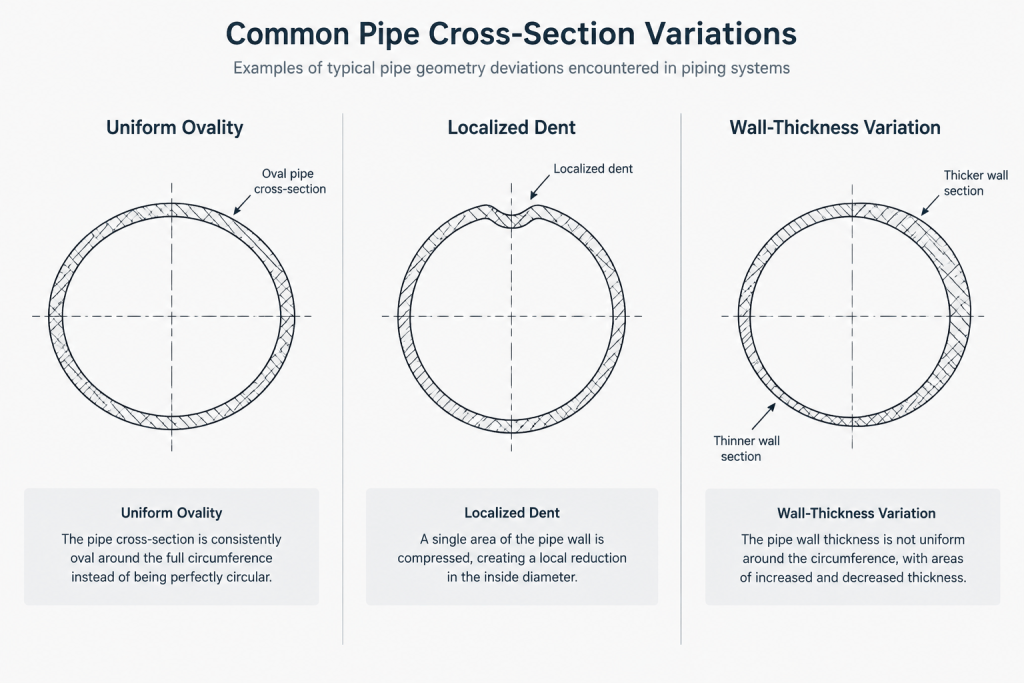
| Condition | What varies | Typical CAD implication |
|---|---|---|
| Outside-diameter variation | The measured OD differs from its nominal or specified basis | Can affect fit-up, sleeves, clamps, and tight clearances |
| Ovality or out-of-roundness | The diameter changes with measurement direction at one section | A circular model may not represent the actual extreme envelope |
| Wall-thickness variation | The wall is not uniform around the circumference or along the pipe | Can affect bore alignment and weld-end preparation |
| Centerline curvature | The pipe is bowed or not straight along its length | Can affect routing, support contact, and field alignment |
| Local dent or distortion | A limited area is displaced rather than the whole section becoming oval | May require localized survey geometry and engineering review |
A pipe can have an acceptable average diameter while still being noticeably out of round. It can also be nearly round but have an overall diameter near a permitted limit. Similarly, a round outside surface does not prove that the bore is concentric or that wall thickness is uniform.
Why pipe becomes out of round
Ovality can originate during manufacture or develop later. The likely cause depends on the pipe product, fabrication process, service history, and handling method.
- Forming and welding: Formed pipe can retain cross-sectional variation from rolling, forming, sizing, and seam welding operations.
- Bending: A bend can experience flattening or distortion, especially around the bend region. The outside and inside of the bend are also subject to different forming strains.
- Handling and storage: Lifting methods, stacking loads, transport restraints, or impacts can distort pipe, particularly where the wall is relatively flexible.
- Fabrication forces: Clamps, strongbacks, fit-up tools, heat input, and weld shrinkage can change the local shape of an end or shell.
- External loading: Soil, supports, attachments, thermal forces, or other imposed loads may alter the cross-section.
- Existing damage or deterioration: Dents, corrosion, or prior modifications can produce irregular geometry that is not well described by a simple oval.
The cause matters because a uniform oval section, a local dent, and a distorted weld end may require different evaluation methods. A CAD drafter should not classify visible deformation as acceptable ovality without engineering or inspection input.
Where ovality matters in piping work
Butt-weld fit-up
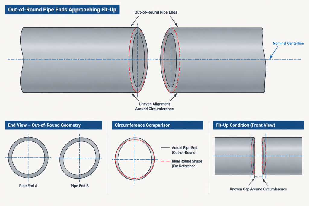
Out-of-round pipe ends can create uneven internal or external alignment when two components are brought together. Rotating one component may improve alignment in one area while making it worse elsewhere. Fitters may use approved correction methods, but the drawing should not assume that a nominal circular end guarantees uniform fit-up.
This issue is particularly important when joining components from different manufacturing routes, matching pipe to formed fittings, or connecting new work to existing pipe whose actual end geometry is unknown.
Mechanical connections and close-fitting components
Clamps, couplings, seals, sleeves, split attachments, and other components that engage the pipe outside surface may depend on the actual OD envelope and roundness. A nominal-size CAD symbol cannot confirm compatibility. The selected component manufacturer’s requirements and the measured pipe condition must be checked.
Supports and attachments
Saddles, shoes, guides, and clamps are often modeled against a nominal circular surface. Significant distortion can change contact patterns, create gaps, or shift the apparent pipe center. For fabricated attachments, field dimensions or templates may be more reliable than dimensions extracted only from the design model.
Penetrations and tight clearances
A nominal pipe OD is usually adequate for general routing, but it may not represent the largest actual radial extent of an out-of-round section. This can matter at sleeves, seals, equipment openings, closely spaced structural steel, or other interfaces with limited clearance. Insulation, coatings, movement, installation tolerance, and survey uncertainty also need separate allowances.
Inspection tools and internal devices
Internal tools, cleaning devices, inspection equipment, and inserted components interact with the real bore rather than the nominal CAD cylinder. Bore restrictions may result from ovality, weld profile, wall-thickness variation, misalignment, deposits, or deformation. A clear nominal bore in the model is not proof of physical passage.
How ovality should be handled in CAD
For ordinary design development, do not remodel every pipe as an ellipse. Doing so adds complexity without improving most drawings and may imply a level of survey knowledge that does not exist. Maintain nominal circular geometry unless actual deformation affects an interface, an installation decision, or a required record.
When actual geometry is important, use a controlled workflow:
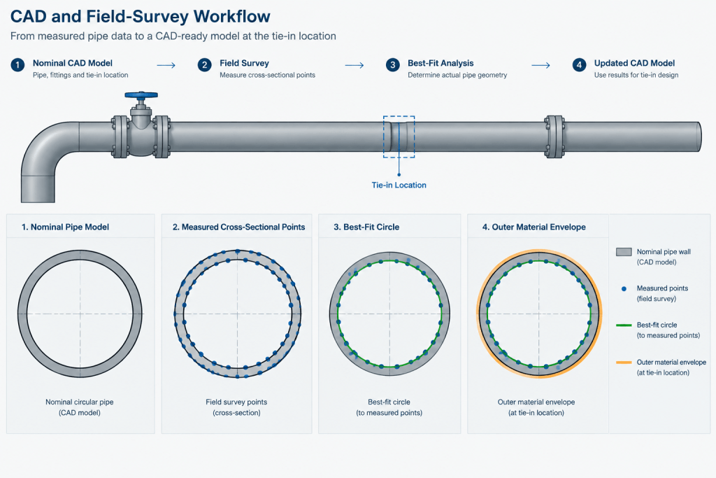
- Identify the location of the measured cross-section along the pipe.
- Record the maximum and minimum measured diameters and their directions.
- State whether dimensions are outside, inside, or derived measurements.
- Record measurement conditions if coatings, temperature, access, or surface condition may affect the result.
- Keep measured values separate from nominal database dimensions.
- Model a surveyed envelope or local cross-section only where it supports a defined coordination purpose.
- Label reconstructed or assumed geometry clearly so it is not mistaken for a complete scan.
For point-cloud or field-survey work, a best-fit cylinder can be useful for establishing a centerline, but it may smooth over local distortion. Review residual deviations or cross-sectional slices where fit-up and clearance are sensitive. A best-fit centerline and an extreme material envelope answer different questions.
Drawing and model notes that add value
A useful note should explain the required verification without declaring an unverified acceptance limit. Depending on the project, documentation may call for field verification of pipe roundness at a tie-in, confirmation of actual OD before ordering a clamp, or a dimensional survey before fabricating a close-fitting sleeve.
Avoid vague notes such as “make fit” when the interface depends on measured geometry. Instead, identify the component or location to be checked, the responsible party under the project workflow, and the point at which the information is needed. Any correction, reforming, or acceptance decision should be governed by the applicable engineering and quality procedures.
Practical review checklist
- Is the model based on nominal geometry, field measurements, or scan data?
- Does the connection involve a close-fitting clamp, sleeve, seal, or coupling?
- Could out-of-roundness affect butt-weld alignment or bore continuity?
- Is the reported value based on OD, ID, circumference, or a fitted shape?
- Are the maximum and minimum directions documented?
- Is a local dent being incorrectly treated as general ovality?
- Do fabrication details rely on a perfectly circular contact surface?
- Has the governing acceptance method been identified by engineering or quality personnel?
- Are measured conditions kept separate from nominal component-library data?
Use nominal geometry intelligently
Perfect circles remain the practical basis for piping CAD. They support consistent routing, dimensions, component placement, and material extraction. The limitation is not the circular model itself; the problem arises when nominal geometry is treated as proof of actual manufactured or installed shape.
Pipe ovality and out-of-roundness should therefore be managed as interface and verification issues. Use nominal models for general design, measured envelopes for sensitive locations, and the governing project documents for acceptance. That distinction keeps CAD efficient while giving fabrication and field teams the information needed where real geometry matters.
Turning field geometry into usable design information
A field report becomes more useful when it distinguishes the measured condition from the engineering decision. Survey personnel can document the cross-section, measurement direction, surface condition, and location. Engineering or quality personnel can then compare that information with the governing requirements. CAD personnel should represent only the geometry needed for the stated coordination or fabrication purpose.
This separation helps prevent a surveyed shape from being treated as an acceptance verdict. It also prevents nominal library geometry from overriding reliable field information at a sensitive interface.
Choose geometry for the decision being made
- Routing and material takeoff: Nominal circular geometry is normally the practical representation.
- Fit-up review: Cross-sectional measurements and end alignment may be more relevant than a general pipe centerline.
- Clamp, sleeve, or support detailing: The outside material envelope and local surface condition may control the interface.
- Internal passage review: Bore geometry, weld profile, deposits, and local restrictions require consideration beyond nominal outside geometry.
- Existing-condition documentation: Measured, reconstructed, and assumed geometry should remain clearly distinguishable.
Preserve traceability during handoff
When measured geometry enters a model, its origin should remain identifiable. Model notes or associated records should indicate whether the shape came from direct measurement, survey points, scan interpretation, or a simplified reconstruction. The record should also identify where the cross-section was observed, because a condition at one location does not automatically describe the entire pipe length.
The most reliable workflow treats CAD as a communication tool rather than an inspection certificate. The model can show an interface risk, a surveyed envelope, or a required verification point, while formal acceptance remains with the applicable engineering and quality process.
Frequently asked questions
Can a CAD model confirm that a pipe is acceptably round?
No. Standard piping models usually show nominal circular geometry. Acceptance must be based on the applicable specification, inspection method, project requirements, and verified measurements.
Should an out-of-round pipe always be modeled as an ellipse?
No. An ellipse may be a useful simplified representation when measured deformation affects a specific interface, but it can also conceal dents, irregular distortion, or changes along the pipe. Nominal geometry should generally remain in place unless surveyed shape information supports a defined purpose.
Is pipe ovality the same as a dent?
No. Ovality generally describes directional diameter variation across a cross-section. A dent is a localized displacement and may not resemble a consistent oval. The conditions should not be combined without inspection and engineering review.
Can an acceptable average diameter prove that a pipe is round?
No. An average can conceal a larger diameter in one direction and a smaller diameter in another. The measurement method and directional results are necessary to understand the cross-section.
What should be recorded during a field check?
Useful records identify the measurement location, whether the dimensions relate to the inside or outside surface, the maximum and minimum directions, relevant surface conditions, and the method used. The governing procedure determines what additional documentation is required.
Does a best-fit cylinder show the full material envelope?
Not necessarily. A best-fit cylinder can support centerline reconstruction, but it may smooth over local or directional deviations. Cross-sectional slices or an extreme envelope may be needed where actual clearance or contact controls the design decision.