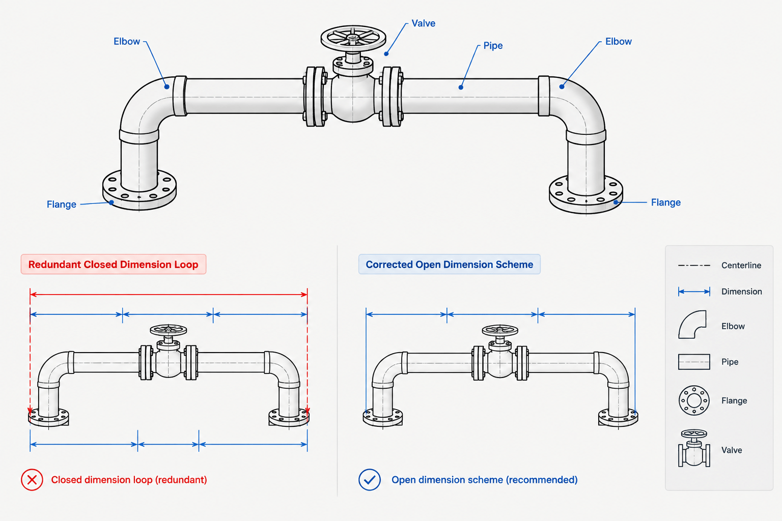
Closed dimension loops in piping drawings are a drafting-control problem, not simply a mathematical mistake. The modeled geometry may be internally exact while the issued drawing unintentionally requires a fabricator to satisfy several dependent dimensions as though each were independently controlling.
The practical objective is to communicate which interfaces must be achieved, where measurements originate, and which displayed dimensions are provided only for checking. The following guide explains how to recognize overdefined piping geometry and revise the dimension scheme without losing useful fabrication information.
A piping drawing can look fully defined and still be difficult to fabricate. One common cause is a closed dimension loop: a set of dimensions that controls the same geometry through more than one path. Because real components, welds, cuts, and assemblies have tolerances, every dimension in the loop may not be achievable at the same time.
This problem appears in spool drawings, isometrics, equipment connection details, support layouts, and tie-in packages. It is especially easy to create when dimensions are added directly from an exact CAD model without first deciding which measurements actually control fabrication.
A good dimensioning scheme does more than describe geometry. It establishes design intent, identifies fixed interfaces, and gives the fabricator a practical sequence for laying out the work.
What Is a Closed Dimension Loop?
A closed dimension loop exists when a drawing defines a complete dimensional path between features and also states the overall dimension across those same features. The intermediate dimensions and the overall dimension become mathematically dependent.
For example, imagine a spool with two fitting takeouts and a straight pipe segment. If the drawing controls both fitting positions, the straight cut length, and the total face-to-face length, the same assembly has been defined in multiple ways. The CAD values may add up perfectly, but actual fitting dimensions, end preparation, weld gaps, alignment, and fabrication tolerances may produce a different result.
The issue is not that overall dimensions are inherently wrong. The issue is presenting both the parts and the total as independent requirements without indicating which dimensions control.
Why Exact CAD Geometry Does Not Solve the Problem
CAD systems can calculate geometry with far greater precision than a shop can cut, fit, weld, and inspect a piping assembly. That precision is useful for coordination, but it does not eliminate manufacturing variation.
Real assemblies may be affected by:
- Permitted variation in manufactured fittings and flanges
- Pipe cutting and end-preparation variation
- Weld joint setup and fit-up conditions
- Angular alignment and flange rotation
- Weld shrinkage and heat distortion
- Field dimensions that differ from design-model assumptions
- Measurement taken from different physical or theoretical points
If every CAD-derived measurement is shown as controlling, the drawing can impose requirements that are internally inconsistent in practice. Adding decimal places does not resolve this conflict; it can make the intended level of control less clear.
Controlling and Reference Dimensions
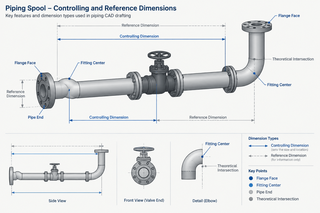
The drafter should separate dimensions that govern fabrication from dimensions supplied only for checking, coordination, or general information.
Controlling dimensions
A controlling dimension defines a required location, length, orientation, or interface. Fabrication and inspection decisions are based on it. Typical examples include an equipment nozzle interface, a field tie-in location, a flange-face location, or the centerline of a branch that must align with another system.
Reference dimensions
A reference dimension reports a useful measurement derived from other controlling geometry. It may help with handling, checking, estimating space, or understanding the assembly, but it should not create an additional fabrication requirement.
Reference status must be unmistakable under the project drafting convention. Parentheses, a reference abbreviation, a note, or another approved graphical method may be used. The project should apply one method consistently rather than relying on the reader to infer intent.
Common Dimensioning Methods
| Method | How it works | Primary concern |
|---|---|---|
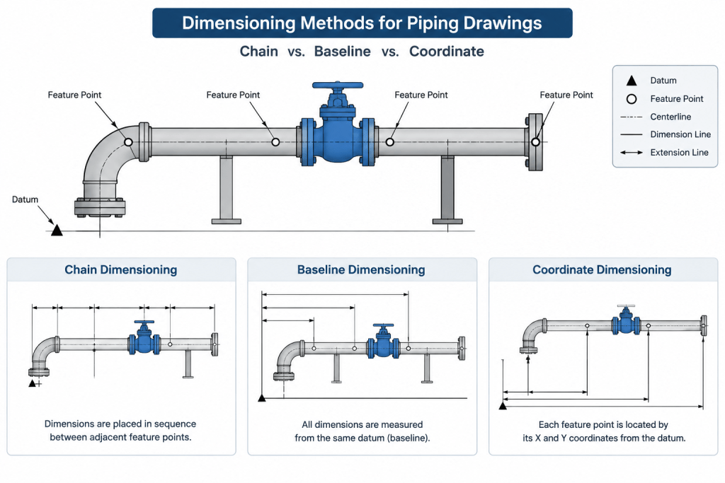
| Chain dimensioning | Each feature is located from the preceding feature. | Variation can accumulate along the chain. |
| Baseline dimensioning | Several features are located from one common datum. | The datum must be physically meaningful and clearly identified. |
| Coordinate dimensioning | Features are located using plant, equipment, or drawing coordinates. | The coordinate system and feature point must be unambiguous. |
| Overall dimensioning | The total extent between two end features is shown. | It can close a loop when all intermediate segments are also controlled. |
| Reference dimensioning | A derived value is shown for information or checking. | It must not be mistaken for an independent requirement. |
No single method is best for every drawing. A practical piping detail often combines them, but each dimension should have a defined purpose.
Choose the Functional Interfaces First
Before placing dimensions, identify the features that must connect to something outside the spool or assembly. These functional interfaces usually deserve priority over convenient model measurements.
Potential controlling interfaces include:
- Equipment nozzle faces and centerlines
- Existing piping tie-in points
- Flanged battery-limit connections
- Pipe rack or structure datums
- Branch centerlines serving fixed equipment
- Support locations governed by structural steel
- Points reserved for field adjustment or final fit
Next, determine which feature is the principal datum and which end, if any, can absorb normal fabrication variation. A spool fixed rigidly at both ends requires different planning from a spool connected at one fixed nozzle and completed with a field-fit segment.
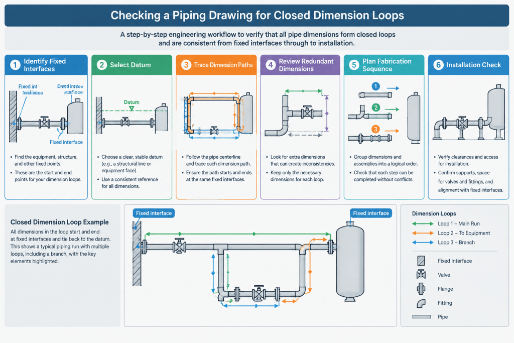
A Practical Workflow for Removing Closed Loops
1. Identify every fixed endpoint
Mark equipment connections, tie-ins, and other interfaces that cannot move. Confirm whether their locations are verified field conditions, vendor information, or design assumptions.
2. Trace each dimension path
Follow the dimensions from one end of the assembly to the other. If the reader can reach the same feature through two complete paths, inspect the drawing for a closed loop.
3. Select the governing path
Choose the dimensions that best communicate how the assembly should be fabricated and installed. The governing path should follow functional requirements rather than whichever dimensions are easiest to extract from CAD.
4. Remove or downgrade redundant dimensions
Delete dimensions that provide no useful information. Where an overall measurement is helpful for checking or transport planning, retain it as a clearly identified reference rather than an additional controlling value.
5. Define measurement points
State whether a dimension terminates at a flange face, pipe end, fitting center, theoretical intersection, support centerline, or another feature. A dimension can appear open mathematically while remaining ambiguous physically.
6. Review the fabrication sequence
Consider how the shop will cut, fit, tack, weld, and inspect the spool. A dimensioning scheme that follows the assembly sequence is generally easier to use than one organized only for visual symmetry.
7. Check installation logic
Confirm that the installed spool can meet its fixed interfaces without treating a reference value as exact. Where field verification or final adjustment is required, communicate that requirement through the project’s established documentation process.
Typical Piping Scenarios
Flange-to-flange spools
Controlling every fitting location, each straight segment, and the total flange-face distance can overdefine the spool. Decide whether the flange faces or the internal component locations are functionally dominant. Internal measurements that are merely derived may not need to be controlling.
Equipment nozzle connections
The nozzle face and centerline are often critical interfaces, but the equipment data must be verified before fabrication. Dimensions should also distinguish the nozzle datum from adjacent fitting centers and theoretical intersections.
Branches between fixed systems
A branch may need to align with equipment while the run connects to fixed headers. This creates several competing interfaces. Breaking the work into suitable spools or identifying an adjustment location may be more practical than trying to control every segment within one closed dimensional network.
Supports and structural interfaces
A support location can be dimensioned from piping geometry, structural steel, or plant coordinates. Mixing these references without a hierarchy can produce subtle loops and conflicts. Use the datum that reflects the actual installation interface and coordinate it with the responsible discipline.
Do Not Use Notes to Hide Poor Dimensioning
General notes can explain conventions, but they should not be used to rescue an overdefined drawing. A statement telling the fabricator to verify all dimensions does not identify which requirement takes priority when values conflict.
Similarly, a broad field-fit note is not a substitute for defining the limits of field adjustment. The drawing should communicate which interface is fixed, which dimension is informational, and where variation is intended to be accommodated.
Review Checklist
- Are the functional interfaces clearly identified?
- Is there a meaningful datum for the dimensioning scheme?
- Can any feature be located through more than one complete controlling path?
- Are overall dimensions controlling or reference, and is that status clear?
- Are flange faces, fitting centers, pipe ends, and theoretical intersections distinguished?
- Does the drawing reflect a practical fabrication and installation sequence?
- Have unverified vendor and field dimensions been identified appropriately?
- Are coordinate and linear dimensions consistent with the same model geometry?
- Could a fabricator reasonably determine which requirement governs if variation occurs?
Dimension Intent Matters More Than Dimension Quantity
A heavily dimensioned piping drawing is not necessarily a complete drawing. Too many controlling dimensions can make an assembly less buildable by creating requirements that compete with one another.
The better approach is to establish functional datums, control the interfaces that matter, and label derived measurements as reference information. When dimensions reflect fabrication sequence and installation needs, the drawing becomes easier to interpret, inspect, and coordinate—even though it may contain fewer dimensions than the original CAD-generated detail.
Applying the Review to Drawing Revisions
Removing a closed loop should be treated as a change to fabrication intent, not as a cosmetic cleanup. Before deleting or reclassifying a dimension, confirm why it was shown and whether another discipline, vendor document, inspection activity, or installation plan depends on it.
A useful review compares the piping model, drawing dimensions, interface information, and planned assembly sequence. If they communicate different controlling points, the discrepancy should be resolved before release rather than left for the shop to interpret.
Preserve traceability when intent changes
When a previously controlling dimension becomes reference information, the revision record should make the changed hierarchy understandable. Reviewers need to recognize that the geometry may be unchanged even though the fabrication requirements have been clarified.
Check the drawing after model updates
Associative dimensions can move or recalculate when modeled components are replaced, fittings are reoriented, or spool boundaries change. That behavior does not confirm that the resulting dimension scheme remains suitable. Repeat the loop review whenever a revision affects datums, interfaces, component locations, or field-fit strategy.
Review connected documents together
A spool drawing may appear properly dimensioned in isolation while conflicting with an isometric, equipment connection detail, support drawing, or coordinate schedule. The governing datum and measurement point should remain consistent across the documents used to fabricate and install the same assembly.
Questions for a Fabrication-Focused Drawing Review
- Which dimensions would the shop use first to lay out the assembly?
- Which interfaces will inspection verify as mandatory?
- Does every controlling dimension terminate at an identifiable physical or theoretical point?
- Can normal variation be accommodated without violating another stated requirement?
- Are reference measurements visually distinct under the project convention?
- Do the drawing, model, and installation plan use the same datum hierarchy?
- Would a revision to one component create a new dependent path?
The final test is whether a fabricator can determine what must be held, what may vary, and where that variation is intended to go. If the drawing cannot answer those questions without assumption, its dimensional intent needs further clarification.
Frequently Asked Questions
Is an overall spool dimension always a closed-loop problem?
No. An overall dimension becomes problematic when it is shown as an independent controlling requirement while a complete set of controlling intermediate dimensions defines the same geometry. It may remain useful when clearly identified as reference information or when selected as part of the governing dimension path.
Can a closed dimension loop exist when the displayed values agree?
Yes. Agreement in the CAD model only shows that the nominal geometry is mathematically consistent. Fabrication variation can prevent every dependent dimension from being achieved simultaneously.
Should redundant dimensions simply be deleted?
Delete dimensions that add no practical value. A redundant measurement that supports checking, handling, coordination, or installation may be retained if its reference status is unmistakable under the project drafting convention.
What is the difference between a datum and a reference dimension?
A datum establishes an origin or controlling basis for locating features. A reference dimension reports information derived from controlling geometry and does not create a separate fabrication requirement.
Why are measurement points important?
Terms such as flange face, pipe end, fitting center, support centerline, and theoretical intersection describe different locations. If the dimension endpoint is unclear, the shop and designer may interpret the same dimension differently even when no mathematical loop is present.
Can coordinate dimensions and linear dimensions create a loop together?
Yes. If both methods independently control the same feature from different origins, they can overdefine its location. Their hierarchy and common datum relationship must be clear.
Who should decide which dimension controls?
The decision should follow approved project responsibilities and the functional needs of fabrication, inspection, installation, equipment connection, and interdisciplinary coordination. It should not be left to an unsupported shop-floor assumption.