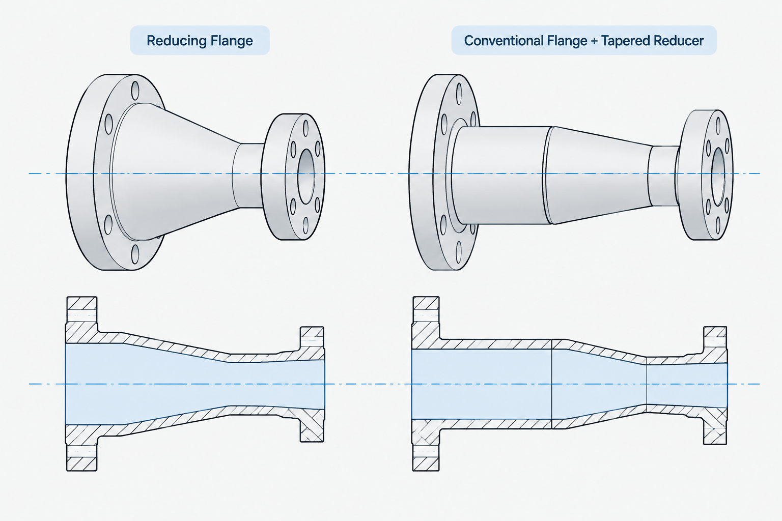
Choosing a reducing flange vs. a reducer and flange is not merely a matter of drawing preference. Although both arrangements can connect a larger flanged interface to a smaller pipe, they create different component boundaries, connection planes, bore profiles, weld locations, and material requirements.
This guide explains how to distinguish the arrangements in piping CAD, what information each model must retain, and which issues should be resolved before a designer substitutes one configuration for the other.
A pipe size transition near a flanged connection can often be represented in two ways: a reducing flange or a separate pipe reducer followed by a conventional flange. These arrangements may connect the same nominal pipe sizes, but they are not geometrically or functionally interchangeable.
The choice affects the bore transition, overall length, flange drilling, weld locations, material takeoff, procurement, maintenance, and flow behavior. A CAD model that treats the options as equivalent can therefore create conflicts even when its connecting centerlines appear correct.
What Is a Reducing Flange?
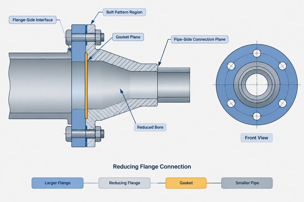
A reducing flange combines a flanged joint and a size transition in one component. Its external flange geometry and bolt pattern correspond to the larger mating flange, while its pipe-side connection or bore corresponds to the smaller pipe size.
This distinction is important when selecting or building a CAD component. The mating face is controlled by the flange connection, not simply by the size of the downstream pipe. A generic small flange enlarged graphically to meet a larger flange is not an adequate representation.
The exact hub, bore, facing, end preparation, and transition geometry depend on the selected component type and manufacturer or governing dimensional basis. Designers should not infer these details from a schematic symbol.
What Is a Reducer-and-Flange Assembly?
A reducer-and-flange assembly uses two identifiable components:
- A conventional flange matching the adjoining flanged connection
- A separate concentric or eccentric reducer that transitions to the smaller pipe
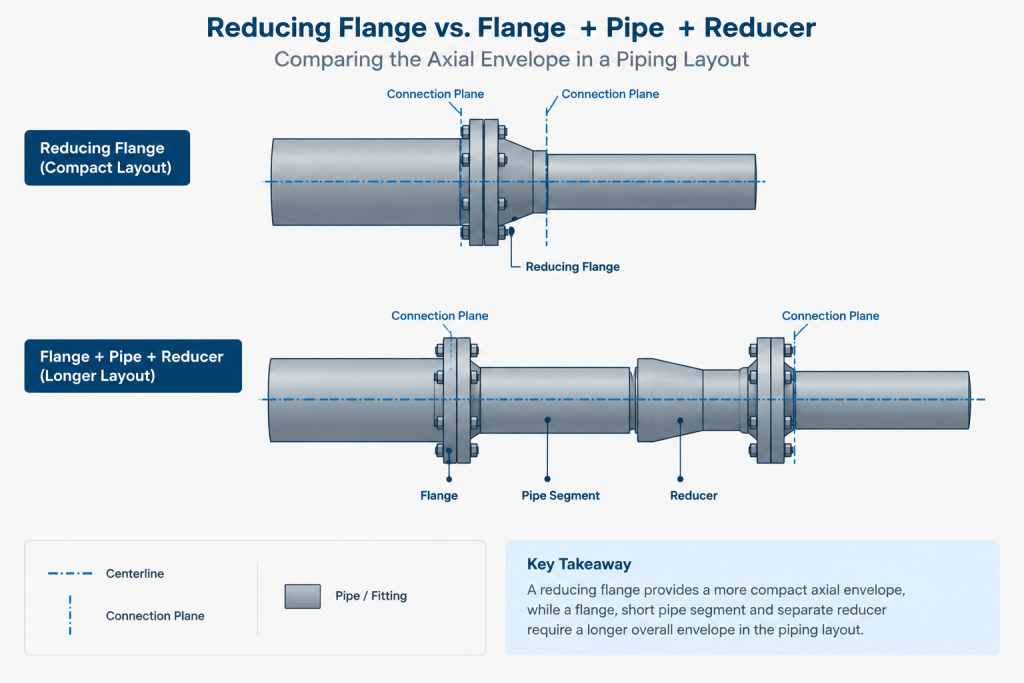
A short piece of pipe may also be required between the flange and reducer, depending on the flange type, reducer end preparation, welding requirements, and fabrication approach. This means the modeled assembly may contain more than two physical items even when a diagram shows only a flange and reducer.
Because the size change occurs away from the gasket face, this arrangement normally consumes more axial space than a compact reducing flange. It also creates separate welds and inspection locations that must be included in the isometric and bill of materials.
Key Differences for Layout and Detailing
| Design issue | Reducing flange | Reducer and flange |
|---|---|---|
| Size transition | Integrated into or immediately behind the flange | Occurs in a separate reducer |
| Axial space | Often more compact | Requires the reducer length and possibly an intervening pipe segment |
| Flange drilling | Must match the larger mating flange connection | Controlled by the conventional flange selected for the joint |
| Bore profile | Component-specific and potentially abrupt | Defined primarily by the selected reducer geometry |
| Weld count | May reduce the number of separate welded components | Usually introduces additional component joints |
| Material takeoff | Listed as a distinct reducing-flange item | Lists the flange, reducer, and any required pipe piece separately |
| Replacement | Requires the correct reducing component | Uses separate, more readily identifiable component functions |
| CAD library needs | Requires size-pair-specific connection data | Can use conventional flange and reducer records |
Why the Bore Transition Matters
The outside envelope is only part of the comparison. The internal flow path can differ significantly between a reducing flange and a tapered reducer. A compact flange may place the change in bore close to the joint face, while a separate reducer distributes the transition over its body length.
That difference may matter where the line carries solids, where pressure loss is important, where drainage must be maintained, or where an instrument or equipment nozzle is sensitive to nearby flow disturbance. These are engineering considerations rather than drafting preferences.
The CAD designer should show enough geometry to make the transition location visible and should flag any substitution that changes the intended bore profile. A reducing flange should not be introduced merely to solve a space problem unless the piping specification, process requirements, and procurement basis permit it.
Concentric and Eccentric Transition Options
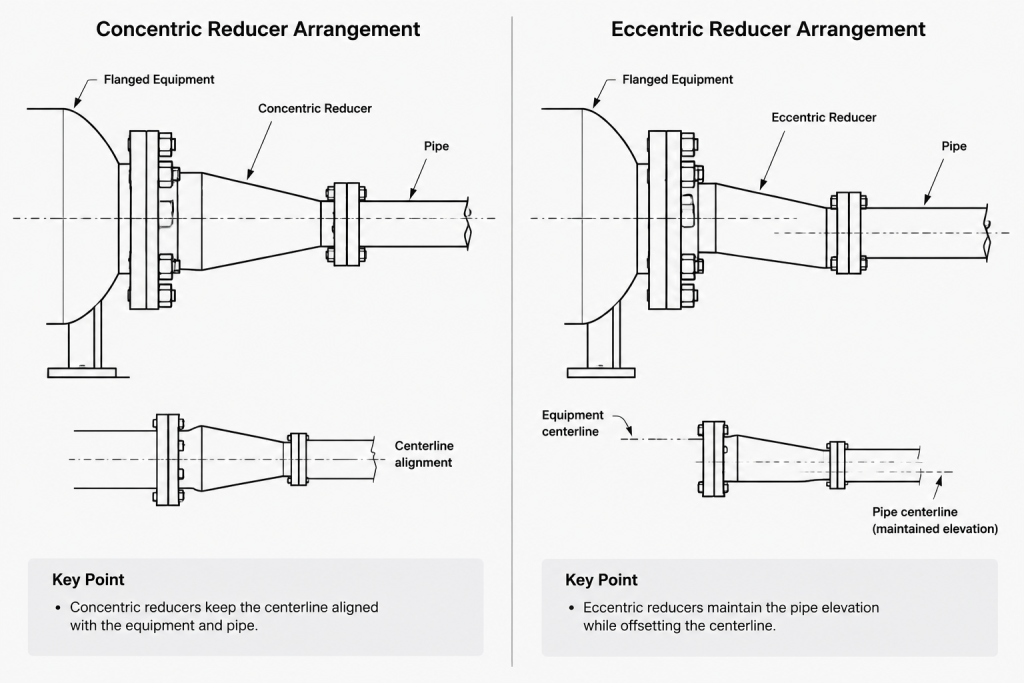
A reducer-and-flange assembly can use either a concentric reducer or an eccentric reducer when the project specification allows it. This provides control over the alignment of the smaller pipe relative to the larger connection.
A concentric reducer maintains a common centerline. An eccentric reducer offsets the smaller pipe and may be oriented to preserve a selected top, bottom, or side elevation. The required orientation depends on service, drainage, vapor-pocket concerns, equipment geometry, and project practice.
A reducing flange does not automatically provide the same offset control. Many configurations are treated as concentric connections, but the actual component geometry must be checked. If an offset transition is required, the selected component must explicitly support that geometry rather than relying on a misleading CAD symbol.
How to Model a Reducing Flange Correctly
Define both connection sizes
A reducing-flange component record should identify the flange-side nominal size and the pipe-side nominal size independently. A single nominal-size field is insufficient because it cannot describe both interfaces.
Place ports at physical connection planes
The flange port should be located at the gasket contact plane used by the project model. The pipe-side port should be located at the actual weld, socket, or threaded connection plane. Do not place both ports at the same point simply because the component is compact.
Keep drilling and facing data with the flange side
The bolt pattern, facing, and flange class belong to the mating flange interface. The reduced pipe size should not overwrite those properties in the catalog or block attributes.
Represent the bore separately from the outside shape
In a detailed model, the internal opening should reflect verified component information. For less detailed drawings, a simplified envelope may be acceptable, but the component description must still make the reduction clear.
How to Model a Reducer-and-Flange Assembly
Build the arrangement as separate catalog items rather than stretching a combined graphic. Start at the established flange face and work toward the smaller line:
- Insert the correctly rated and faced flange.
- Apply its verified connection length or hub geometry.
- Add any required straight pipe segment.
- Insert the specified concentric or eccentric reducer.
- Set the reducer orientation and downstream centerline or elevation.
- Confirm weld locations and calculate pipe cut lengths from physical connection planes.
This method preserves component identity and produces a more reliable bill of materials. It also allows reviewers to distinguish the flange joint from the size transition.
Common CAD and Specification Errors
- Using the smaller size for the bolt pattern: The flange drilling must match the mating flange, even though the connected pipe is smaller.
- Treating a reducing flange as a class adapter: A size-reducing flange does not automatically connect different pressure classes, facing systems, or flange standards.
- Replacing a reducer assembly without checking length: The substitution changes connection planes and may affect equipment clearance, spool dimensions, and support locations.
- Ignoring the reducer orientation: Replacing an eccentric reducer with a concentric reducing flange can change the intended pipe elevation or drainage behavior.
- Omitting component identity from the material list: A generic flange description may not communicate the two nominal sizes required for procurement.
- Assuming catalog availability: Not every size pair, material, flange type, facing, or class is commercially available under every piping specification.
Selection Questions for a Design Review
Before finalizing either arrangement, the project team should answer the following questions:
- What flange size, class, facing, and drilling must mate with the adjoining component?
- What smaller pipe size and end connection are required?
- Is a concentric transition acceptable, or is an eccentric offset required?
- Is the internal transition suitable for the service and equipment connection?
- Does the piping material specification permit the selected component?
- Is verified dimensional information available for the exact reducing flange?
- How does the choice affect spool length, field fit-up, inspection, and access?
- Can procurement obtain the component in the required material and configuration?
- Will maintenance personnel be able to identify and replace it correctly?
Practical Documentation Guidance
On a P&ID, both solutions may appear as a size change near a flanged connection, so the diagram alone may not establish the physical arrangement. The line list, piping specification, equipment connection data, model, isometric, and material list must be reconciled.
On an isometric, identify a reducing flange with both connection sizes and the required flange properties. For a separate assembly, show the flange and reducer as distinct items with their applicable welds. If an eccentric reducer is used, document its orientation through the project’s established notation rather than relying only on the drawn shape.
The final choice should be based on engineering intent and verified component data. Compact geometry can be valuable, but reducing flanges and reducer-and-flange assemblies should never be exchanged solely because they connect the same nominal sizes.
A Practical CAD Review Workflow
A reliable comparison begins at the mating flange face rather than at the downstream pipe centerline. Review the required flange interface, trace the physical transition to the smaller pipe, and confirm where each connection or weld plane occurs. This prevents a visually aligned model from concealing an incorrect component arrangement.
Check component identity before geometry
Determine whether the specification calls for a distinct reducing flange or for separate flange and reducer items. The model description, catalog record, item tag, and material takeoff should all communicate the same arrangement.
Compare connection planes
Replacing a reducer-and-flange assembly with a reducing flange can move the pipe-side connection plane. Review adjoining spool dimensions, equipment clearance, support relationships, and access before accepting the change.
Review the transition axis
Confirm whether the smaller pipe remains on the larger connection centerline or requires an offset. A separate eccentric reducer can preserve a selected alignment, while a reducing flange must not be assumed to provide equivalent offset geometry.
Validate model properties independently
Flange-side and pipe-side data should be checked as separate interfaces. The flange connection controls mating properties such as drilling and facing, while the pipe side controls the reduced connection and its end preparation. Combining these into one generic size property can cause catalog, connectivity, and reporting errors.
Reconcile deliverables
Compare the model against the isometric, piping specification, equipment connection information, and material list. A change is incomplete if the geometry is updated but the component description, weld records, or procurement data still represent the previous arrangement.
When Simplified Graphics Are Acceptable
A simplified symbol or envelope may be useful in an early layout model, provided it does not obscure the component type or create false connection locations. The simplification should retain enough metadata to distinguish a reducing flange from a conventional flange followed by a reducer.
Before fabrication documentation is issued, replace assumptions with verified component geometry and connection information. Manufacturer data, the project piping specification, and the governing dimensional basis should control the final model rather than a schematic appearance.
Frequently Asked Questions
Is a reducing flange the same as a flange attached to a reducer?
No. A reducing flange combines the flanged interface and size change in one component. A reducer-and-flange assembly contains separate component functions and may also require an intervening pipe piece.
Which size controls the reducing-flange bolt pattern?
The bolt pattern must correspond to the mating flange interface. It should not be selected solely from the smaller downstream pipe size.
Can a reducing flange replace an eccentric reducer and flange?
Not automatically. An eccentric reducer may preserve a required top, bottom, or side alignment. A reducing flange can be substituted only when its verified geometry, the piping specification, and the service requirements support the intended transition.
Why can two correctly aligned CAD arrangements still be different?
Matching centerlines do not establish equivalent bore geometry, axial length, weld locations, component identity, or connection planes. These details affect spool fabrication, material reporting, clearance, and flow behavior.
Should a reducing flange have one nominal-size property or two?
Its component record should distinguish the flange-side nominal size from the pipe-side nominal size. A single undifferentiated size field cannot describe both interfaces adequately.
How should the alternatives appear in a bill of materials?
A reducing flange should appear as its own identifiable component. A separate assembly should report the flange, reducer, and any required pipe piece as distinct items according to the project’s material reporting practice.
Can a reducing flange also adapt flange class or facing?
A size reduction does not by itself establish compatibility between different flange classes, facings, or dimensional systems. Every mating property must be verified separately.