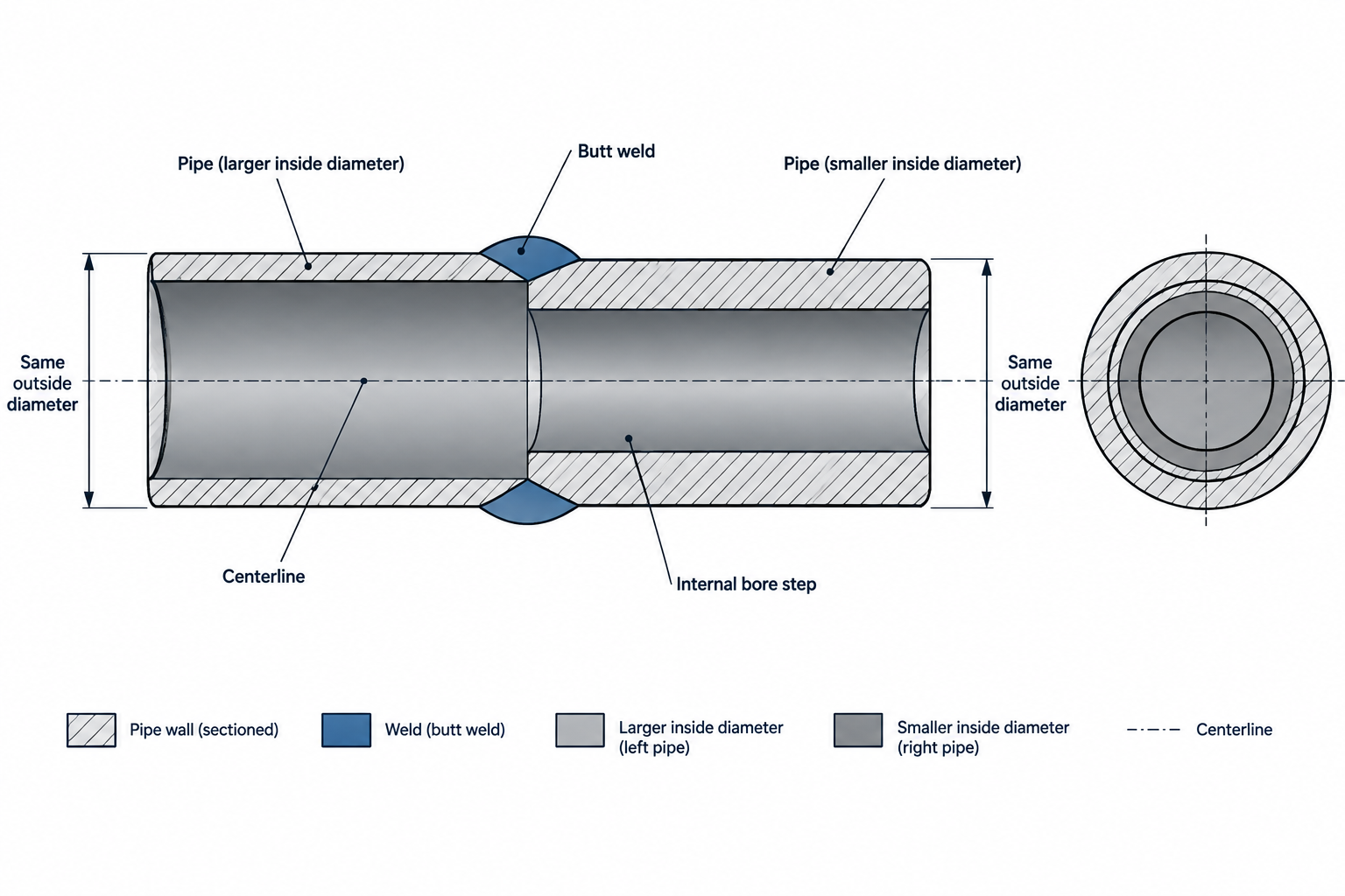
Pipe bore mismatch is an interface-control issue that may remain hidden in a centerline model or an externally accurate CAD assembly. A sound review must look beyond nominal size and outside alignment to the wall, internal geometry, end preparation, and source data for each component.
This guide explains how piping designers and drafters can recognize potential mismatch at butt-weld connections, record uncertainty, coordinate engineering review, and carry an approved resolution into models and fabrication documents. It is a checking framework rather than a substitute for the governing code, project specification, welding procedure, equipment drawing, or manufacturer data.
A butt-weld connection can look perfectly aligned from the outside while containing a significant internal step. This condition, commonly described as pipe bore mismatch or internal misalignment, occurs when the inside diameters of the adjoining components are not the same.
Bore mismatch may appear between two pipes, between pipe and a fitting, at a reducer, or where piping meets a valve, flange, nozzle, or specialty item. Some differences are intentional and acceptable within the governing design basis. Others require machining, tapering, a transition piece, or a change in component selection. A centerline-only CAD model will not reveal the difference, so designers must compare the underlying size, wall, bore, and end-preparation data.
Why outside alignment does not guarantee bore alignment
For a given nominal pipe size, commonly used pipe schedules generally retain the same nominal outside diameter while changing wall thickness. As wall thickness increases, inside diameter decreases. Two components can therefore share an outside profile and centerline but have different bores.
This relationship is especially important at butt-welded joints. The CAD geometry may show two matching cylinders, yet the actual flow passage can contain an internal shoulder. Simplified fittings and valves may also be modeled with nominal ports rather than verified end bores, making the visual model even less reliable for this check.
In conceptual layouts, simplified geometry is often appropriate. During detailed design and fabrication preparation, however, bore compatibility must be checked from controlled piping data rather than inferred from appearance.
Common causes of pipe bore mismatch
Different pipe schedules or wall designations
A schedule transition within the same nominal size changes the pipe inside diameter even when the outside diameter remains consistent. This may occur at a piping specification break, a corrosion-resistant section, a high-design-condition segment, or an equipment connection.
Pipe-to-fitting wall differences
A butt-weld fitting designation does not automatically prove that its end bore will match every connected pipe. Fitting dimensions, tolerances, end preparation, manufacturing method, and specified wall all affect the actual connection. The fitting description and the project material specification must be checked together.
Flange and valve end bores
Weld-neck flanges, butt-weld valves, and specialty components may have end preparations intended for particular mating conditions. The connecting pipe schedule alone is not enough to establish compatibility. Purchased-item data may be necessary, especially when the component bore is manufacturer-dependent.
Equipment nozzles
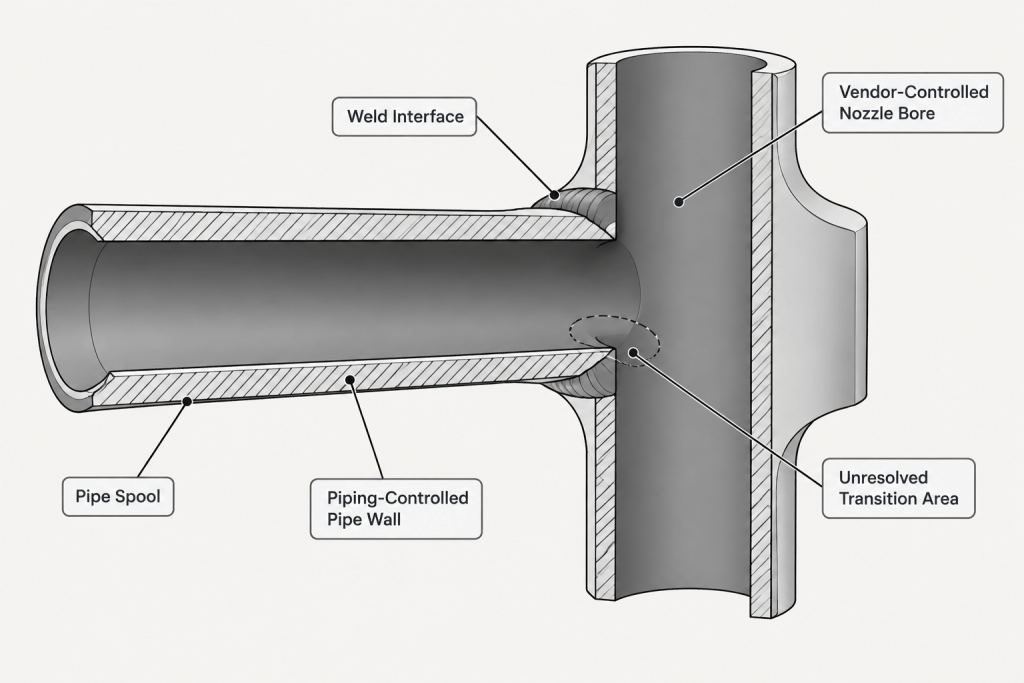
Nozzle neck wall thickness and bore may differ from the connecting process pipe. Equipment drawings often control the nozzle geometry, while the piping team controls the attached spool. That interface requires deliberate coordination rather than an assumption that matching nominal sizes produce matching internal diameters.
Material or specification changes
A material class change can bring a different wall basis, corrosion allowance, fitting type, or component construction. Even if the line number and nominal size remain unchanged, the internal geometry may change across the specification boundary.
Internal mismatch versus eccentric alignment
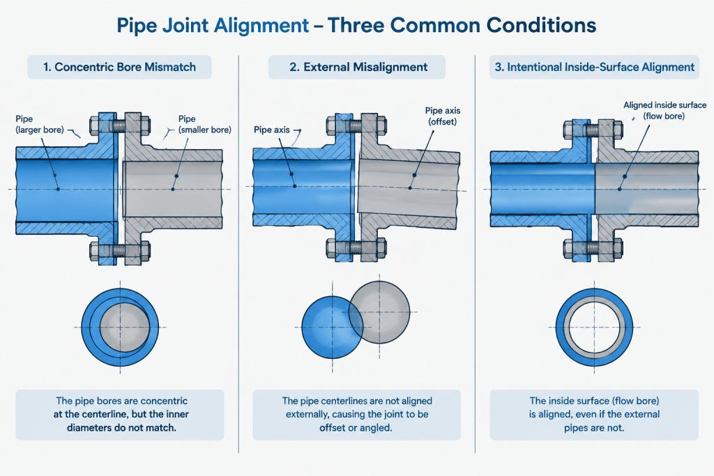
Not every unequal bore should be interpreted in the same way. Two components can be concentrically aligned, placing the internal step evenly around the circumference. They can also be externally offset or intentionally aligned along one surface, producing a larger local step on the opposite side.
These conditions have different drafting and fabrication implications:
- Concentric bore difference: The component centerlines align, but the internal diameters differ.
- External misalignment: The outside surfaces or centerlines do not align as intended.
- Intentional surface alignment: One internal or external surface is held flush for process, drainage, fabrication, or layout reasons.
- Out-of-roundness or tolerance effect: Nominally compatible parts do not align uniformly in the actual fit-up.
A drawing note should describe the intended condition clearly. Phrases such as “match bore,” “align inside surface,” or “transition by machining” must not be added casually; their applicability depends on engineering review, available wall, component design, fabrication procedure, and governing requirements.
How bore mismatch affects a piping system
The importance of an internal step depends on the service and the joint. A mismatch may influence local flow behavior, pressure loss, erosion exposure, drainage, cleaning, piggability, product retention, or inspection access. It may also affect weld geometry and the method used to examine the finished joint.
This does not mean every bore difference is automatically unacceptable. Acceptance criteria are established by the applicable code, project specification, engineering assessment, welding requirements, and component data. CAD personnel should identify the condition and route it to the appropriate discipline rather than inventing a tolerance or repair detail.
A practical bore-mismatch checking workflow
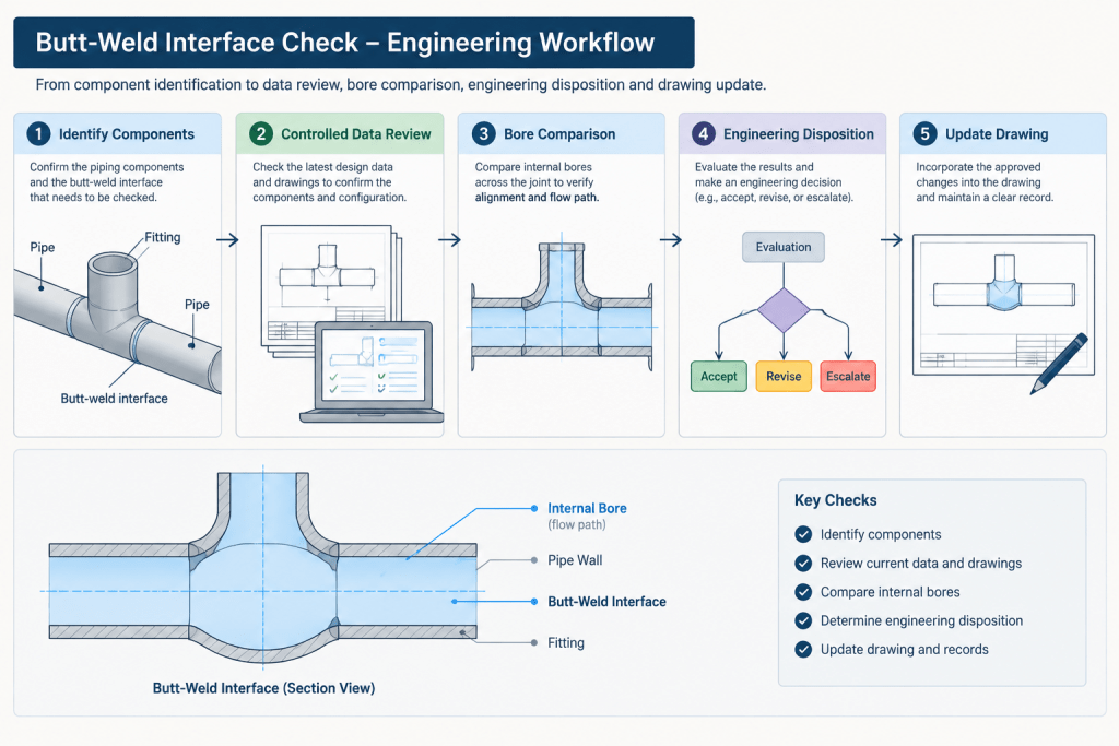
1. Identify the connection pair
Record exactly what meets at the weld: pipe to pipe, pipe to fitting, pipe to flange, pipe to valve, or pipe to nozzle. Confirm nominal size and end-connection type on both sides.
2. Confirm the controlling data
Review the line class, pipe schedule or wall designation, fitting description, component specification, equipment drawing, and available vendor information. Do not calculate a purchased component bore from its outside envelope unless the controlling documentation permits that approach.
3. Compare bore-related dimensions
For pipe, inside diameter is related to outside diameter and wall thickness. For fittings and equipment connections, use verified end dimensions or approved product data. Keep nominal values separate from minimum-wall, ordered-wall, and measured conditions.
4. Check both ends of asymmetric components
Reducers, transition pieces, specialty valves, and fabricated items can have different conditions at each end. A single component property may not describe both weld interfaces.
5. Classify the result
| Observed condition | Recommended CAD response |
|---|---|
| Bores are compatible based on controlled data | Retain the normal joint representation and record the verified source. |
| Difference exists but acceptance is not established | Flag the connection for piping or welding engineering review. |
| Engineered transition is required | Model and document the approved transition, machining, or replacement component. |
| Vendor bore is unknown | Mark the interface as pending and avoid presenting nominal geometry as verified. |
| Field dimensions control | Show the hold point, field verification requirement, or fit-up responsibility in the appropriate document. |
6. Update affected deliverables
If the resolution changes physical geometry, update the model, isometric, bill of materials, weld information, spool limits, and any related interface drawing. If it is handled only by a fabrication instruction, ensure that the note is controlled and associated with the correct joint.
Representing bore transitions in CAD
The level of representation should match the purpose of the model. A plant layout model generally does not need every internal surface, while a fabrication detail may need enough information to define the transition.
- Centerline model: Use attributes or review reports to compare wall and end data because the geometry cannot show the bore.
- Solid model: Model actual bores only when reliable dimensions are available and the detail supports coordination or fabrication.
- Isometric drawing: Add an approved note, joint reference, or detail callout where special end treatment is required.
- Fabrication detail: Show the controlled surfaces, transition concept, and required references without assuming an unverified shop method.
- Equipment interface drawing: Distinguish vendor-controlled nozzle data from piping-controlled spool data.
Avoid making a model look more precise than its source information. An accurately rendered but assumed bore can conceal uncertainty instead of resolving it.
Questions to include in design review
- Do the two sides have the same nominal size but different wall designations?
- Is the fitting or flange end bore verified, or merely inferred from a generic CAD block?
- Does a specification break occur at or near the weld?
- Is the equipment nozzle bore shown on a controlled drawing?
- Could machining affect minimum required wall or component integrity?
- Does the service impose special concerns for drainage, cleaning, erosion, or internal inspection?
- Has the proposed treatment been reviewed by the responsible engineering and welding disciplines?
- Are both ends of the component checked separately?
Key drafting principle
Nominal size and matching outside geometry do not prove that two butt-weld ends have matching bores. Reliable detailing requires a connection-by-connection comparison of wall thickness, inside geometry, end preparation, and controlled component data.
The CAD model should communicate what is known, identify what remains unverified, and show only transitions that have been approved for the project. Treating pipe bore mismatch as an interface check—not simply a modeling detail—helps prevent fit-up surprises and keeps engineering, procurement, fabrication, and field documentation aligned.
Managing bore data through the design workflow
Bore compatibility should be treated as a controlled connection property rather than an assumption attached to nominal size. The review record should identify the joint, the components being compared, the source used for each bore-related value, and whether the result is verified, pending, or resolved by an approved transition.
Keep source status visible
Generic CAD geometry, preliminary vendor outlines, piping specifications, approved equipment drawings, and measured field information do not carry the same authority. Model attributes and review comments should distinguish calculated pipe geometry from manufacturer-controlled or field-controlled dimensions. This prevents an assumed internal surface from being reused as though it were verified.
Coordinate changes across disciplines
A proposed bore transition can affect more than the model. Piping engineering may need to confirm component selection, welding engineering may need to review joint preparation, procurement may need revised purchasing information, and fabrication may need a controlled detail or instruction. Equipment interfaces also require clear ownership between the piping and equipment documentation.
Close the review loop
- Identify the exact weld interface and the controlling documents.
- Record missing or conflicting bore information as an open item.
- Avoid adding machining, tapering, or alignment instructions before approval.
- Update every affected deliverable after the disposition is accepted.
- Retain the approved source or review reference with the project record.
The objective is not to model every internal surface. It is to ensure that the design record accurately communicates what is known, what remains uncertain, and what treatment has been authorized.
Pipe bore mismatch FAQ
Can matching nominal pipe sizes still have different bores?
Yes. Nominal size does not define the complete internal geometry. Different wall designations, component constructions, end preparations, and manufacturing tolerances can produce different bores at a butt-weld connection.
Can outside alignment confirm that a butt-weld joint is internally aligned?
No. Components may share a centerline and outside profile while forming an internal step. Bore-related data must be checked independently.
Should a drafter calculate the bore of a valve, flange, or equipment nozzle?
Not unless the controlling project documentation permits that method. Purchased components and equipment interfaces may require approved manufacturer or equipment data rather than an inference from the external envelope.
Does every bore difference require machining?
No. The required disposition depends on the applicable design basis, component data, service conditions, welding requirements, and engineering review. A designer should flag the condition rather than prescribe an unsupported shop treatment.
How should an unknown component bore appear in project documentation?
It should remain clearly identified as unverified or pending. Nominal CAD geometry should not be presented as confirmed internal geometry, and any dependent fabrication detail should be held until controlled information is available.
When should an internal transition be modeled?
Model it when reliable dimensions and an approved treatment are available and when the added detail supports coordination or fabrication. Otherwise, use controlled attributes, notes, review items, or interface references appropriate to the deliverable.
What records should be updated after a mismatch is resolved?
Update the affected model and all applicable isometric, material, weld, spool, fabrication, and interface documentation so that the approved disposition remains consistent across deliverables.